Did you also combined the impedance of the loudspeaker itself?Am I missing something here?
As well as the bafflestep etc.
Well, the impedance of the speaker should be covered in the equivalent circuit, which is why I put the high pass tweeter side in..eventually being able to work all the way back to an amplifier. (Did I mention scope creep).
The baffles have not been included, since right now I am really just at the point of understanding what the system is doing. And...I am having some issues using the CLOSED section to
The baffles have not been included, since right now I am really just at the point of understanding what the system is doing. And...I am having some issues using the CLOSED section to
Sorry - the last part got cut off.
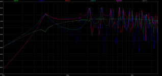
I am finding the the CLOSED circuit does not appear to actually do anything.
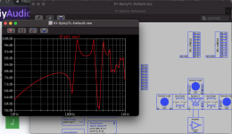
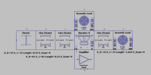
simple line with closed end:

here is the line with the closed end removed:

here, i made the end left segment a 1cm2 by 20cm hole (which should act closed to these frequencies, right?:

wait: there is more...version 1.7, with closed end:

matching circuit verson 2.0.2:

Sweet, right? ...but without the closed section...same:

So it LOOKS like all the line segments are by defaulted ended UNLESS attached to another line segment? Does the CLOSED circuit do anything, or can we just assume all line are closed unless they have a load attached?
I am finding the the CLOSED circuit does not appear to actually do anything.
simple line with closed end:
here is the line with the closed end removed:
here, i made the end left segment a 1cm2 by 20cm hole (which should act closed to these frequencies, right?:
wait: there is more...version 1.7, with closed end:
matching circuit verson 2.0.2:
Sweet, right? ...but without the closed section...same:
So it LOOKS like all the line segments are by defaulted ended UNLESS attached to another line segment? Does the CLOSED circuit do anything, or can we just assume all line are closed unless they have a load attached?
Attachments
Jeff, it may seem like nonsense, but the equivalent electrical circuit of a "closed end" is acoustically an open circuit. The end of a segment (if not loaded in any way) then automatically behaves as a closed end. The structure of SpictTL2.0 made the "offset" block superfluous, so I created the "closed" block because, especially when placed between two segments, it helps to understand graphically how the design is structured.

Hi woodo, I didn't know Qspice, I will take a look at it, but I am very comfortable with LTspice
Notwithstanding, would you be considering using Qspice at all at some point if development continues?
https://www.qorvo.com/
SpicyTL is designed to work at low frequencies where there is no phenomenon associated with directivity@slocum
Just curious, but will there ever be any kind of bafflestep simulation involved?
That way it makes the whole simulation a little bit more useful. 🙂
Also in addition, I assume simulating things like dipoles or even cardioids also wouldn't be a problem?
I was aware of that 🙂SpicyTL is designed to work at low frequencies where there is no phenomenon associated with directivity
Most bafflestep models can applied on the same piston range level.
Bafflestep is not related to directivity.
Well, I guess to a sense it is, but it still works in the piston range domain 🙂
The BSC operates right in the transition zone. I don't think it would be too difficult to implement in SpicyTL a model that takes this into account, but I've never been overly concerned with this topic for two reasons:Most bafflestep models can applied on the same piston range level.
Bafflestep is not related to directivity.
Well, I guess to a sense it is, but it still works in the piston range domain 🙂
1 - Even though I'm designing with SpicyTL, for everything beyond optimizing the low-frequency response, I use LDS/ALAB: a very powerful software that allows you to define the design of a speaker system in almost every aspect. For simulating diffractions, LDS/ALAB uses the Vanderkooy model, which indirectly allows you to also predict the 'baffle step' effect. The correspondence with the simulations is impressive.
2 - I believe that the 'baffle step' effect is greatly overestimated and that in a domestic environment with regular speakers (excluding therefore speakers without baffles or with very wide front panels) one should not take it into account at all.
2 - I believe that the 'baffle step' effect is greatly overestimated
Obverused?
dave
Hi Andrea,
I recently found your work and really appreciate what you’ve done with your site, software, and information on TL speakers. I’ve been playing around with the spicytl and am wondering what is proper way to model a coupling chambers with one and two tubes (in separate systems). I see in your articles using a volume parameter that doesn’t seem to be implemented anymore and can’t seem to find any current examples of these. With the current v2.0 I have found a number of different interpretations of these two systems that produce different results. I will provide examples shortly but was curious what the official method is.
The two systems in question:
|=[_]==o
[_]==o
Thanks!
Nolan
I have made, and will upload as soon as possible, some minor refinements to the model, but nothing that can yield appreciably different results in normal contexts; it's more of a perfectionist tendency linked to an ever-improving knowledge of Spice. The model is perfectly stable and functional, and although I have some ideas that I would like to develop in the future, at the moment I don't feel the need to make substantial changes.I was curious how things are going over here and if there is any new development in progress?
Thank you, Nolan,Hi Andrea,
I recently found your work and really appreciate what you’ve done with your site, software, and information on TL speakers. I’ve been playing around with the spicytl and am wondering what is proper way to model a coupling chambers with one and two tubes (in separate systems). I see in your articles using a volume parameter that doesn’t seem to be implemented anymore and can’t seem to find any current examples of these. With the current v2.0 I have found a number of different interpretations of these two systems that produce different results. I will provide examples shortly but was curious what the official method is.
The two systems in question:
|=[_]==o
[_]==o
Thanks!
Nolan
I believe the best way to simulate those configurations is through the use of Transmission Line segments with different cross-sections. The Volume block is very useful (it should still be present in the versions available for download), but in this case, you would lose the information related to the total length of the system.
I look forward to more details, see you soon,
Andrea
Thank you, Nolan,
I believe the best way to simulate those configurations is through the use of Transmission Line segments with different cross-sections. The Volume block is very useful (it should still be present in the versions available for download), but in this case, you would lose the information related to the total length of the system.
I look forward to more details, see you soon,
Andrea
Hi Andrea,
Thank you for the response!
Thank you for the clarification on the advantages of using a Line over a Volume, I had my suspicion that was the case, and will continue using Line. I still get different results depending on how I structure it.
When you describe the offset for the coupling chamber as a " small mounting offset along the line, usually made inevitable by the shape we intend to give the speaker, in which direction do you mean and what do you consider the chamber and tube. Is the offset towards the face of the speaker or along the line?
Attachments
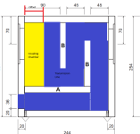
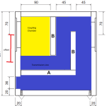

For 'offset', we mean the distance between the speaker axis and the beginning of the TL, therefore you should reason as shown in the attached figure.Hi Andrea,
Thank you for the response!
Thank you for the clarification on the advantages of using a Line over a Volume, I had my suspicion that was the case, and will continue using Line. I still get different results depending on how I structure it.
When you describe the offset for the coupling chamber as a " small mounting offset along the line, usually made inevitable by the shape we intend to give the speaker, in which direction do you mean and what do you consider the chamber and tube. Is the offset towards the face of the speaker or along the line?

Hello everyone , so I have a studio monitor project i have been working on for some time, some really nice people on this forum have been helping me with the Hypex DSP filters but unfortunately I cannot get the measurements correct due to the complex TL design . What I am looking to do is to upload DSP files for a 4th order speaker witch is based around the PMC MB2s . I have all the cab measurements and internal dimensions of the TL CAN anyone one here run the simulation of each drive unit and supply files for DSP upload. ? Many thanks ..
I can’t help on the dsp files but I can suggest you work on the measurements
What seems to be the issue?
What seems to be the issue?
hello, thanks for the reply, so let me give you a brief summary, I actually have all the cabs completed with the drive units in place, I have tried to run REW but for some reason nothing seems to work. My plan is to set everything up in one of my rooms with temporary treatment added, and run some sort of measurement software ? individually measure the drivers, take that info and upload to Hypex amps where i can edit the DSP filters. i have been at this for almost two months now , the main issue is getting the measurements and because I dont have a clue what im doing that puts a spanner in the works , REW is free but at the point because these are studio monitors i think ill have to pay for some sort of more pro software , can you suggest something ? thanks ..What seems to be the issue?
SpicyTL can only be used to define the correct woofer loading, and although you can include the crossover filter in the simulation, you still cannot use it to define a correct crossover between drivers.Hello everyone , so I have a studio monitor project i have been working on for some time, some really nice people on this forum have been helping me with the Hypex DSP filters but unfortunately I cannot get the measurements correct due to the complex TL design . What I am looking to do is to upload DSP files for a 4th order speaker witch is based around the PMC MB2s . I have all the cab measurements and internal dimensions of the TL CAN anyone one here run the simulation of each drive unit and supply files for DSP upload. ? Many thanks ..
There is no way to properly design a crossover without the possibility of making measurements.
- Home
- Loudspeakers
- Subwoofers
- SpicyTL - Transmission Line Simulation Model