Both versions of SpicyTL received an update regarding the bend model.
Looking at the Figure it is easy to see that, taking into account the variation in section, a volume (that relating to the two triangles) is generated in the simulation which does not exist in reality.
Since it is reasonable to assume that the length actually 'seen' by the acoustic pressure wave is actually less than that measured at the centre of the fold, I applied to the geometric length a correction equivalent to the 'phantom' volume.
This volume, equivalent to the red rectangle in the Figure, for a TL of unit section is (SQRT(2)-1)*l/2 which corresponds to an increase of more than 20%.
In essence, the effective length of the fold would be approximately 83% of the length calculated at the centre.

Hi wodoo, the most significant difference is that with version 2 you can load the speaker from the front as well with TL segments and simulate even very complex projects. It's also possible to simulate multiple projects on the same sheet. In general, the new model is much simpler, and with a good understanding of Spice, truly remarkable results can be achieved.
I see there is a straight section that can be simulated with foam, is there a way to use the foam parameters for tapered reducing and expanding sections? Using the foam certainly quells the ripples in the simulation but I haven't got a feel for how much to use and what it means. I have been having a play on a hypothetical pipe with a few 180 deg bends. Not sure about SL of the bend itself so I just set it it the same as the S_in and S_out which is unlikely to be correct.
Attachments
Last edited:
apologies, first mentions I meant "fibre". Also, in the instructions for the impedance test, is it possible to add a couple of pics or diagrams to explain the process?foam
SpicyTL does not simulate a tapered line filled with 100% fibre. However, one user approximated the simulation of a 100% fibre-filled line with very good results by replacing the foam parameters (c_1 and K_1) with the fibre parameters (c_2 and K_2) and setting S_foam to the average value between S_in and S_out.I see there is a straight section that can be simulated with foam, is there a way to use the foam parameters for tapered reducing and expanding sections? Using the foam certainly quells the ripples in the simulation but I haven't got a feel for how much to use and what it means. I have been having a play on a hypothetical pipe with a few 180 deg bends. Not sure about SL of the bend itself so I just set it it the same as the S_in and S_out which is unlikely to be correct.
I'm not sure if I understand correctly, but if the section does not vary in the 180-degree fold, I recommend using two 90-degree folds.
Wow, wow, wow. I just recently picked up the speaker building itch. After building and enjoying a set of Overnight Sensations MTM, of course I went looking to mess around with cabinet design (of course I use a Mac...)...and then I found SPICYLT. Wow, I bought it, I love it....and it made me realize I am an idiot.
OK...so I am NOT an electrical engineer, though I do have a rudimentary knowledge of circuits. And I had never heard of LT Spice until now. So very sorry if this is a naive question.
I am trying, initially to model the current set of speakers that I have built (according to the Paul Carmody design). My thinking here is that I really didn't stuff the fill with any sort of planning at all, and I wanted to see what this might affect.
Attached is the circuit that I created, and the results from the output....
Maybe I am looking for a little hand holding on whether my general approach is sound? Using lines to simulate ports?
More importantly... How do I combine the outputs of the speakers and ports together in a plot so I can see what the overall efficiency of the speaker will be?
Thanks!
-Jeff
Attachments
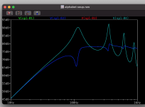
Slocum May chime with sage advice. From memory the spl-sys test point provides the full system output. I’ve only used the free version. The paid version appears to have more options.
From the instructions….
display of the vertical axis: position the mouse on the left vertical axis of the graph and right-click. Select the Bode representation in the drop-down menu and tick Decibel.

There’s also instructions about using fibre and foam on the spicytl webpages but the HornResp approach seems more intuitive to me. Slocum does offers some suggestions on how to sim fibre in a previous post.
From the instructions….
SPL Simulation
Place the probe on the desired “SPL_” test point. If necessary, change thedisplay of the vertical axis: position the mouse on the left vertical axis of the graph and right-click. Select the Bode representation in the drop-down menu and tick Decibel.
There’s also instructions about using fibre and foam on the spicytl webpages but the HornResp approach seems more intuitive to me. Slocum does offers some suggestions on how to sim fibre in a previous post.
Last edited:
Thanks Woodo, worked like a charm. Don't ask me why I never thought to click there!
I appreciate the help.
I appreciate the help.
Very interesting stuff indeed!
Basically just the lumped element part from like AKABAK.
I like the modular aspect of it, although this could also be potentially introduce errors maybe?
How free are we just to mix and match certain blocks to create other system ideas?
Basically just the lumped element part from like AKABAK.
I like the modular aspect of it, although this could also be potentially introduce errors maybe?
How free are we just to mix and match certain blocks to create other system ideas?
I think we are relatively free to do so within the boundary of the provided free version and available blocks but looks like most development is happening with the commercial version. Not sure whether these will be incorporated into the free version over time. I have only played around to see how it works. @slocum pops in occasionally to answer questions. There is an email address at the end of the the following webpage with the name of the copywriter. Not sure if it is Slocum 🤔.How free are we just to mix and match certain blocks to create other system ideas?
https://transmissionlinespeakers.com/en/spicytl-english/
It has been about 3.5 decades since I dealt with complex circuits...so take this with a huge grain of salt...
I would assume that one could model all the various circuit equivalents in the free version as well.
My view on these things is that you pay a bit for the convenience. A bit more for a calibrated system of sorts wrt the PU foam. And a bit more to encourage continued development.
My suspicion is that the folks who really use this have their own special circuits developed and calibrated around their particular needs. I can certainly see the rabbit hole one could fall into. Especially when including the crossover into the circuit.
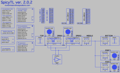
Hello Wodoo, the version 2.0 of SpicyTL is much more streamlined from a structural point of view, making it much easier to update the model or create new blocks and functions. The free version can simulate the most common transmission line configurations and is probably even more intuitive to use, but developing new features is really too costly in terms of time and effort.I think we are relatively free to do so within the boundary of the provided free version and available blocks but looks like most development is happening with the commercial version. Not sure whether these will be incorporated into the free version over time. I have only played around to see how it works. @slocum pops in occasionally to answer questions. There is an email address at the end of the the following webpage with the name of the copywriter. Not sure if it is Slocum 🤔.
https://transmissionlinespeakers.com/en/spicytl-english/
The great strength of SpicyTL 2.0 is the ability to also front-load the speaker, and I realized the real potential of the software only when I was presented with projects/ideas from users who purchased it. But I repeat: the free version has been downloaded by thousands of users and is perfect for all projects that are commonly referred to as transmission lines.
Slocum is the nickname I chose several years ago when I registered, and yes, it's me.
Andrea
Jeff, I thank you for your enthusiasm. To understand whether you have modeled the TL correctly, it would be helpful to have a draft of the design.Wow, wow, wow. I just recently picked up the speaker building itch. After building and enjoying a set of Overnight Sensations MTM, of course I went looking to mess around with cabinet design (of course I use a Mac...)...and then I found SPICYLT. Wow, I bought it, I love it....and it made me realize I am an idiot.
OK...so I am NOT an electrical engineer, though I do have a rudimentary knowledge of circuits. And I had never heard of LT Spice until now. So very sorry if this is a naive question.
I am trying, initially to model the current set of speakers that I have built (according to the Paul Carmody design). My thinking here is that I really didn't stuff the fill with any sort of planning at all, and I wanted to see what this might affect.
Attached is the circuit that I created, and the results from the output....
Maybe I am looking for a little hand holding on whether my general approach is sound? Using lines to simulate ports?
More importantly... How do I combine the outputs of the speakers and ports together in a plot so I can see what the overall efficiency of the speaker will be?
Thanks!
-Jeff
My apologies Andrea, your sign off line is clearly there but I missed it.yes, it's me.
Andrea
Notwithstanding, would you be considering using Qspice at all at some point if development continues?developing new features is really too costly
https://www.qorvo.com/
I think I am at the point where I could use help, and/or therapy. My plan of a simple speaker "upgrade" has suffered from some scope creep. The plan started out simple - build a set of Paul Carmody Classix 2.5, and then look at a different cabinet geometry. My foggy recollection tells me that the crossover needs to be considered in all of this, although I have not yet seen anyone overtly discuss. But that is how I started out, and perhaps it is a mistake?
Paul's site: (so, so kind of him to share)
https://sites.google.com/site/undefinition/floorstanding-speakers/classix2-5?authuser=0
Below are
1) a first rough approximation model with speakers in a box

2) system modeled with Xover - currents flowing into speakersView attachment 1215336
3) system with Xover - modeled SPL

Am I missing something here? This response is not what I expected. Note that if I just look at the cabinet response or the current flow through the capacitor I would have expected a much flatter response. Or, should I be expecting something much more flat?
Also - while I can measure current flow into the tweeter, the output SPL did not seem to be making sense. Probably because of Piezo? If this is the case, does it mean that the equivalent circuit load of the tweeter is wrong and another approach is needed?

I am just seeking to understand what is going on here in terms of modeling before I think of venturing out into the woods alone. This is not supposed to open up a discussion on the particular model (which I look forward to building regardless of any of the above....)
-Jeff
Paul's site: (so, so kind of him to share)
https://sites.google.com/site/undefinition/floorstanding-speakers/classix2-5?authuser=0
Below are
1) a first rough approximation model with speakers in a box
2) system modeled with Xover - currents flowing into speakersView attachment 1215336
3) system with Xover - modeled SPL
Am I missing something here? This response is not what I expected. Note that if I just look at the cabinet response or the current flow through the capacitor I would have expected a much flatter response. Or, should I be expecting something much more flat?
Also - while I can measure current flow into the tweeter, the output SPL did not seem to be making sense. Probably because of Piezo? If this is the case, does it mean that the equivalent circuit load of the tweeter is wrong and another approach is needed?
I am just seeking to understand what is going on here in terms of modeling before I think of venturing out into the woods alone. This is not supposed to open up a discussion on the particular model (which I look forward to building regardless of any of the above....)
-Jeff
I think that is like 99% of the people on this forum, whahahaha 😀 😀 😀therapy. My plan of a simple speaker "upgrade"
- Home
- Loudspeakers
- Subwoofers
- SpicyTL - Transmission Line Simulation Model