Since the doublet intensity falls as frequency decreases, your useful frequency range is about equal to your doublet SNR. Nonlinearity cuts into BW in the same way, so 10% even order THD will imbalance the doublet and so reduce the frequency range to a 1:10 ratio. So a lot of bits aren't really needed, only enough to cover the frequency range you want. And that can be extended through averaging.
I tried using 2 different ADCs at once, and both are in agreement on the midrange, So this does not appear to be a sampling error.
This is strange. I can rule out almost everything except that the acoustic doublet actually has this LF content. I guess the question is then, why?
Perhaps the electrodes are burning and I need a higher melting point metal or one less prone to oxidize?
Last edited:
The discharge is a thermal event so maybe arranging a way to cool the gap would help. A fan? The air compression will be affected by the heat I think.
I'm using a sheet of copper clad and discharging directly into the clad. I'll be playing some more with it but not for a couple of weeks. I have some travel coming up.
I'm using a sheet of copper clad and discharging directly into the clad. I'll be playing some more with it but not for a couple of weeks. I have some travel coming up.
But Scott Wurcer was able to do it seemingly without having any of these issues.
My doublet only had 8 samples at 96KHz but the mic response to it seemed to go for about 250us. The amplitude was very low and I tried to achieve pulse source and mic being out in free space as much as possible. I have no idea what you are trying to achieve with any large flat surfaces near to mic. Earthworks is very clear that there should be no reflective surfaces near the source or mic. Also I was only trying to go above 500Hz and out to 20kHz. For my pulse I needed correction for the first Bessel null in the "N" wave but this was small.
Instead of doing the integration in software I tried shunting the EM258 with a 100nF capacitor. I was able to use a longer gap with louder spark. This looks considerably more promising.
The mic needs to be tested with a known acoustic source before and after adding the capacitor, to know it's corner frequency so it can be calibrated out.
So it seems an analog LP filter might be the best option.
The mic needs to be tested with a known acoustic source before and after adding the capacitor, to know it's corner frequency so it can be calibrated out.
So it seems an analog LP filter might be the best option.
Attachments
The inconsistency is driving me mad.
I took several measurements that showed that the midrange rise correlated more with gap length than distance or SPL. Now the anomaly correlates with SPL.
I suppose there is a difference. The anomaly is now below 2KHz whereas before it extended beyond that.
To obscure the 0.5db hump in the pressure response in 1audio's chart, would require a gain compression of about 6%. To limit the doublet BW to 20KHz/1KHz with a 20:1 ratio similarly would require about 5% asymmetric compression. So overload is a possible explanation for the remaining anomaly.
https://content.instructables.com/ORIG/FG3/U9FC/KCBY3DGQ/FG3U9FCKCBY3DGQ.pdf
Richard Lee's PDF here answers some questions. Notably:
1: Electret mics can "block" when overloaded, which must be what I was seeing when the EM258 lost sensitivity. A few different capsules were tested.
2: The Jfets used in Primo mics are probably NEC 2SK4027 or 2SK660. The datasheet shows about 0.5db of gain change per 100uA. At the current signal levels, the Jfet modulation may fall just short of being an explanation for the gain compression and midrange anomaly. It's not out of the question that the EM258 may use a less linear Jfet to make up for the small diaphragm.
Also an important note: The above chart in post #184 appears flat below 1KHz because the corner frequency of the 100nF capacitor is fairly close to the corner frequency of the <2KHz anomaly, so the two curves blend together even though one of them is an aberration. When I reduce the SPL, the <2KHz content actually drops. What is actually significant about the capacitor method is that it allows me to use larger spark gaps without an overwhelming anomaly. High dv/dt at the capsule output appears to worsen the anomaly beyond basic overload behavior.
I am waiting for the next test to see if the anomaly comes back in full force just to prove me wrong after disturbing the spark gap. Then it will be back to square one, yet again.
Last edited:
I couldn't get much good out of the capacitor method because accurate time alignment of the doublets depends on HF SNR, and you lose that with an analog LP filter. That limitation is just specific to my setup. Triggered sparks could eliminate a huge amount of noise.
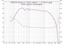
Good tuning of the spark gap along with large sets of averaged sparks can extend the BW below 500Hz. I didn't use a ground plane for this measurement. At 1000 averages the reflections from the tripod are clearly visible on the impulse response.
The closest reflection is 2 feet away, and comes back at 3.4ms. Some of the variation is surely room modes and some of it is also possibly comb filtering from the residual decay of my sparker repeating at 129ms.
If only someone could show me what I'm doing wrong so I can do the same thing but with a resulting calibration curve that resembles the datasheet.
Attachments
Last edited:
I have a triggered spark but it has some jitter due to the nature of the breakdown. I could record the spark in one channel and the current pulse in a second channel. Then some software could use the trigger to normalize the timing of the acoustics. And become a basis for phase measurements. The current pickup need not be too complex- a ferrite ring and a few turns of wire terminated in a low value resistor.
if the software can sort of interpolate the actual time of the impulse between samples and do a coherent multiply the timing accuracy and SNR could be increased significantly.
Unfortunately this is beyond my software skills.
if the software can sort of interpolate the actual time of the impulse between samples and do a coherent multiply the timing accuracy and SNR could be increased significantly.
Unfortunately this is beyond my software skills.
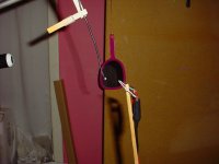
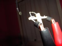
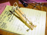
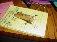
I was trying to think of a mechanism to allow me to precisely control the gap size. I was thinking about pantograph mechanisms I could slap together with sticks. In the end a clothespin was most handy. I use a lot of clothespins and alligator clips.
The spark and screw are equal distances from the fulcrum so with the 0.5mm thread pitch of an M3 screw, I get 0.5mm per turn of movement. I can zero the distance using the continuity tester on the DMM. It might take some swipes between the electrodes with a piece of paper to remove the carbon though.
I am not the least bit confident in it's accuracy but it will allow me to set and maintain a specific spark gap, which has been an enormous issue.
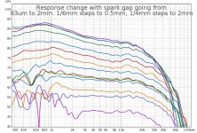
I did a set of reponses going up to 0.5mm in 83um increments, and from 0.25mm to 2mm in 0.25mm increments. You can see how the spectrum changes as the gap increases, notably the midrange rise anomaly that appears above 0.25mm gap.
The spark and screw are equal distances from the fulcrum so with the 0.5mm thread pitch of an M3 screw, I get 0.5mm per turn of movement. I can zero the distance using the continuity tester on the DMM. It might take some swipes between the electrodes with a piece of paper to remove the carbon though.
I am not the least bit confident in it's accuracy but it will allow me to set and maintain a specific spark gap, which has been an enormous issue.
I did a set of reponses going up to 0.5mm in 83um increments, and from 0.25mm to 2mm in 0.25mm increments. You can see how the spectrum changes as the gap increases, notably the midrange rise anomaly that appears above 0.25mm gap.
Attachments
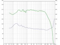
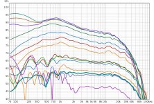
I decided to do a longer test at 167um gap based on the last chart. The new bold trace is 1000 averages at 167um gap. I might try for 83um (1/6th turn of the screw) if the noise floor is willing.
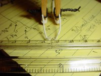
The carbon proves unlikely to remove, but I am satisfied with suspending a piece of aluminum foil between the electrodes and opening the gap until it falls out in order to zero the gap. This aluminum foil is 0.001" thick or 25um, as is standard. Receipt paper is actually even thinner. I was delighted though at seeing the spark jumping a 25um gap.
The carbon proves unlikely to remove, but I am satisfied with suspending a piece of aluminum foil between the electrodes and opening the gap until it falls out in order to zero the gap. This aluminum foil is 0.001" thick or 25um, as is standard. Receipt paper is actually even thinner. I was delighted though at seeing the spark jumping a 25um gap.
Attachments
Last edited:
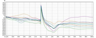
When 4 250 spark sets are averaged to 2 500 spark sets and then one 1000 spark set, the step response converges on an N-wave of period 3ms, which corresponds to a 333Hz BW.
I don't have any 333Hz filters in my signal chain and the EM258 datasheet shows flat response to 60Hz.
Dotted lines are 250 sparks each, dashed lines are 500 sparks each and the solid line is all 1000 sparks.
I think this is a big clue as to where to set the FFT windows, on either side of the step response N-wave is probably a good bet.
As to where this 333Hz time constant comes from I can only guess it has something to do with stored charge at the Jfet gate.
There is some slight RF demodulation apparent before the arrival of the acoustic wave. This could actually be used to determine absolute phase in the same way as recording the spark current would as 1audio proposed.
I had a theory that the RF demodulation primed the jfet to experience higher gate currents and thus cause stored charge, and if so moving the microphone away so that the RF decays before the acoustic wave arrives will bring an improvement. I guess this is something to try if I can reduce the noise floor low enough.
Attachments
I couldn't get much good out of the capacitor method because accurate time alignment of the doublets depends on HF SNR, and you lose that with an analog LP filter.
Are you really that close, all my measurements were at least 5 feet between the mic and spark?
Have you tried phase rotation in the frequency domain to time align? My results are only 512 point FFT's this gives smoothing and removes many comb artifacts. I'm not convinced any very sharp features in the average mic's response are real.
Last edited:
Yes, I get the midrange rise seemingly no matter how far I am from the spark. I can try at a longer distance with a bigger spark (an experiment I've repeated many times but I should do it again). And it is a good time to remind readers of hearing protection...
It should be possible to time align to better than 1 sample using an FFT transform and that is always something I wanted to try, but I'm not sure what software to use.
My charts showing flat response below 1KHz are all bad, I had the filters messed up in my script. I wish it was easy to retroactively delete a bunch of things. I do have a corrective filter to fix the response though. My slicer will only slice the input stream it triggers on, so I have to filter for triggering and then correct. I can verify filtering with a synthesized doublet. I've set it to generate one automatically.
I spent the last 3 days verifying and messing with software to get things working correctly. There were numerous problems. If I am making this look hard, it's because I am just a cowboy. I'm sure if someone else was following along they would have more success than I did.
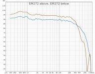
Things are looking better after all the changes though. I followed Scott's advice and set the mic 26" away from a 4mm spark gap. I tested the EM258 and the EM252 (new version of the EM271 with higher max SPL).
Most of the ripples are in the same place for both mics so since they are very different capsule sizes (10mm vs 6mm), I think the differences must be related to reflections from the tripod and spark gap assembly.
I guess the question is when do I stop trusting the datasheet and start trusting my own measurements?
Attachments
Last edited:
It should be possible to time align to better than 1 sample using an FFT transform and that is always something I wanted to try, but I'm not sure what software to use.
I ran my old data and it was easy in Python. Matlab or Octave would also work. A one sample delay is pi radians at fs/2 and a straight line to DC (bin 0). The SNR will matter but 60dB looked like no problem. I don't have multiple pulses saved from years ago so I can't try shifting and averaging them. I used only a 480 point FFT since it gives exact bin answers for 96K sampling, I think interpolating or sample rate converting the data just adds mess for no benefit.
If you want data, here is 500 doublets from the EM272 test. It has a 1KHz 6db/oct lowpass filter to improve triggering and another 60Hz lowpass filter which can be corrected out of the final result, although 60Hz data is unlikely to be useful.
doublet-500.wav.zip - Google Drive
doublet-500.wav.zip - Google Drive
They look pretty good and I'm not sure averaging will do much since the reflective artifacts are the same for each plot. I'll play a little tonight.
Yes, I noticed after looking through them that even a single spark does not differ much from the averaged example, except in the low frequencies. That made me feel kind of dumb. But even if averaging only succeeds in unburying the room modes, maybe it can be useful for room calibration of some sort.
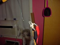
I tried recording a more distant spark many times in the past but I was never satisfied with the results due to interference or various anomalies. I'm a bit puzzled why it worked this time. Maybe next time I set it up the problems will come back. Maybe my random application of ferrite beads hit on something effective. I would like to find a less obstructive way to accurately set the gap to improve the doublet waveform, as I know that flat nearly parallel surfaces are fairly bad for generating standing waves. But without a solid internal corner at the fulcrum of the clothespin maybe it works better than expected and the slender shapes can serve as inspiration for a better design.
It did help that I had to take out the AC while the house was being painted. LF noise is truly awful for doublets. But after I had done all the work to write the averaging program I didn't want to waste the effort, so I persisted in trying to work in absurd conditions.
Yes, I noticed after looking through them that even a single spark does not differ much from the averaged example, except in the low frequencies.
I looked through the first 12 or so after I made no.1 a reference and did not see more than +- 0.1 to 0.2 sample offsets which is the basic noise floor of the process (without another round of work). If they are randomly distributed with small offsets I don't see much to gain for the work.
That was what I thought. With worse SNR the slicer does a worse job at time aligning, but that was not the case here. And some sparks are also duds or misfires. I have way to cull them but some always seem to get through.
It is a given that the clothespin is causing some sort of response aberration, and that is something I can check.
It is a given that the clothespin is causing some sort of response aberration, and that is something I can check.
- Home
- Design & Build
- Equipment & Tools
- Spark calibration of microphones