It depends solely on the spark generator. My generator is inconsistent because it relies on air breakdown voltage which is highly variable. 1audio's generator should be very consistent.
I don't think you could load gunpowder, or ignite it to the precision of a good spark generator.
I don't think you could load gunpowder, or ignite it to the precision of a good spark generator.
Maybe but not for me. Also the SPL is much too high to be useful.
Parts of this do not make sense. I'm pretty confident of the current transformers (Pearson and Stangenes) but the EMI is getting into everything. The Tek THS720 which I have used for years measuring discharges is getting pickup from the arc. Same for the newer scope. I need to figure out a much better isolation for the generator since I seem to get significant noise currents on its power cord. Once those confusors are under control then the controlled times spark would be pretty ideal. its actually an interesting problem but its testing all my measurement reserves.
Parts of this do not make sense. I'm pretty confident of the current transformers (Pearson and Stangenes) but the EMI is getting into everything. The Tek THS720 which I have used for years measuring discharges is getting pickup from the arc. Same for the newer scope. I need to figure out a much better isolation for the generator since I seem to get significant noise currents on its power cord. Once those confusors are under control then the controlled times spark would be pretty ideal. its actually an interesting problem but its testing all my measurement reserves.
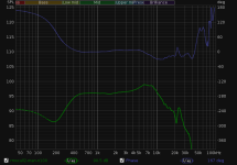
The BW limit is getting lower and lower as I figure out the best way to cull and average recordings. It helps to have a fresh battery and play with electrode approach angle to minimize interference. Group delay shows the impulse response extending to below 1KHz.
I wonder how much the >1KHz stuff is influenced by boundary reinforcement.
I wonder how much the >1KHz stuff is influenced by boundary reinforcement.
Attachments

I think I have figured out where the current is coming from. its a very short peak. The coil is around 7K Ohms of resistance which would limit the current but there is a fair amount of energy stored in the stray capacitance in the HV circuit and very little inductance when it discharges which would explain the high peak current I think. More to explore tomorrow.
I'll try recording a number of discharges in various ways and see what I learn.
I'll try recording a number of discharges in various ways and see what I learn.
One thing I did which helped some is add a ferrite bead right at the spark gap. The one I used was sort of like a 34ohm resistor in parallel with a 1.59uH inductor. With the coilpack, too large a bead would prevent it from sparking altogether. I haven't tried that with the taser. It would be neat if I could get a spark to go across the outside of a bead.
The stray capacitance does seem to play a role especially with a high coil resistance. My taser has much less output resistance than your automotive coil. But I would assume that the coil leakage inductance would dominate in either case. The spark resistance itself increases with spark length, so short gaps would have higher initial discharge current. This agrees with my finding that too small a gap actually increases interference even though it reduces SPL.
Is it possible that the interference is coming from >100MHz noise not caught by your current probe? I remember that with ESD, sparks can generate noise into the GHz powerful enough to destroy small diode junctions.
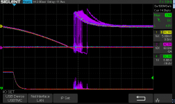
I found that the spark generator was "not well" grounded inside and did a lot with scraping pant and re arranging connections which brought the interference down a lot. Some of the ground return current was getting coupled into the AC ground return. Lots of bad consequences to that. Its much better now. There still is considerable jitter, around 2 uS peak to peak.
You can see from the screencap that the HV starts at the same place and climbs at the same rate (15 KV in around 15 uS) with the overlapping curve. But the breakdown has about 2 uS jitter. For audio measurements 2 uS jitter will not be an issue. I have read that using a laser to trigger the spark would get the lowest jitter and that makes sense.
The spark appears to have 48A peak to peak. If I can find a small cap good for 30 KV (10 pF or so) I can test the current vs cap hypothesis.
The scope still periodically locks up from the EMI but at least it recovers.
Attachments
I did some more fiddling and have confirmed that even RG59 can handle 35KV. I'm reworking the setup and will use some RG6 I think and a sheet of copper clad making the spark at the surface. As the gap opens the voltage and the current goes up. With 3' of radioshack RG59 I have a 13 KV gap and 80 peak amps It gets a lot louder with a larger gap but the probe is really only good for 15KV reliably. 40KV peak if I had the no longer easily available freon.
So spark current increases with gap length. Duh, I should have remembered that.
Is there really no issue with RG59 arcing across the leads through the air at the terminations at 35KV?
Is there really no issue with RG59 arcing across the leads through the air at the terminations at 35KV?
I was surprised that it worked. I stripped the shield back about 2" but the insulation should be fine. A solid poly version would be the best. I also added a 100 Ohm resistor just in front of the spark which seems to provide a much cleaner current pulse. All I have on hand is some pretty junk grade cable from Carol or Radioshack. The Carol cable uses aluminium for the shield and copper coated steeel for the conductor. Neither solder well at all. The RS has a 20% shield coverage. Almost no copper. Still no arcing on the cable.
I need to order some good cable and carbon comp resistors for this. Nothing else will handle the discharge pulses well. Then if the spark is at the surface of the copper clad it should be pretty omnidirectional so I can position the microphones close but above the ground plane. I may bring the cable on the back side and bring it through the PCB for minimal surface disturbance. I have not figured that all out yet.
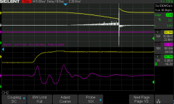
The scope plot is pretty interesting. The 200KW peak power is quite impressive even if only 20 nS long. Actually it could be shorter. The P6015 is only 75 MHz and 5 nS risetime.
I need to order some good cable and carbon comp resistors for this. Nothing else will handle the discharge pulses well. Then if the spark is at the surface of the copper clad it should be pretty omnidirectional so I can position the microphones close but above the ground plane. I may bring the cable on the back side and bring it through the PCB for minimal surface disturbance. I have not figured that all out yet.
The scope plot is pretty interesting. The 200KW peak power is quite impressive even if only 20 nS long. Actually it could be shorter. The P6015 is only 75 MHz and 5 nS risetime.
Attachments
In the NASA spark paper (page 22), they use a needle stuck into a broken off carbon comp resistor as a fast spark protection device. So I suspect the arc might discharge through the carbon comp, or perhaps the voltage coefficient of carbon comp (increases for higher resistance) causes it to act something like a MOV at high voltages. I think this would have to be an advantage if the resistance returns to normal immediately and provides good termination for the coax or whatever you use.
https://apps.dtic.mil/dtic/tr/fulltext/u2/a214199.pdf
The original research paper is paywalled here. Subnanosecond jitter.
OSA | High-speed low-voltage ultraviolet light source
I suppose the microphony of the resistor might matter if it is right at the electrodes.
https://apps.dtic.mil/dtic/tr/fulltext/u2/a214199.pdf
The original research paper is paywalled here. Subnanosecond jitter.
OSA | High-speed low-voltage ultraviolet light source
I suppose the microphony of the resistor might matter if it is right at the electrodes.
Last edited:
I'm using the resistors to terminate the coax and it seems to help. The waveforms look better. I had to repair the P6015 becasuse the connection to the probe had become flakey. I'll need to redo the measurements to be confident going forward. I'm looking for some carbon comp resistors because they have a very high peak power capacity. Working with a big surge generator I have had the privledge of frying a number of alternate resistors.
Any progress on this front?
I was thinking, since the taser already has an internal spark gap to drive the step up trafo, maybe the transformer isn't needed, just bring the internal spark gap out to electrodes. It becomes a smaller spark gap with lower acoustic efficiency and lower voltage, so it should be possible to bring the microphone closer without overloading it, and you don't have to worry about the transformer doing something funny.
Then again the loop currents would be larger, so there is a possibility of magnetic interference.
Hmm, I wonder at what point eddy currents in the microphone capsule might begin to have an effect.
Thanks for bringing me back on track. I have been sidetracked on other projects but hope to get back to this one soon.
One lingering question- what software to extract a frequency response from the spark? Can we get real phase info from it? (reference channel vs. measured channel) Fundamentally it should be possible to get a real response curve from basics, independent of a seperate calibration I hope.
One lingering question- what software to extract a frequency response from the spark? Can we get real phase info from it? (reference channel vs. measured channel) Fundamentally it should be possible to get a real response curve from basics, independent of a seperate calibration I hope.
For all the final work I use REW beta. There is simply nothing else with the same windowing features and useability. The windowing is crucial to get a good result.
I used Audacity or Wavosaur to do the lowpass filtering. Since my EM172 has considerable infrasonic response, a highpass is needed to get good FFTs. I recorded tens or hundreds of doublets and used Audacity to remove the DC component from them all. The order in which you apply filtering and remove DC is very important to not cause drift.
For recording I used Sox on linux. I was able to get it to trigger on each spark, apply some basic culling, and fill a directory with time-aligned doublet recordings. I would open them all in Audacity, manually cull any duds, apply the filters and DC removal, mix them all together and then open in REW. I could batch open the files in REW, time align them all and then let REW combine them, but that did not seem to be necessary as they were sufficiently time aligned to begin with.
Getting rid of the infrasonic noise is problematic. If you remove the DC component (not with a highpass filter but with a sample average), then FFT windowing will actually cause a DC offset which can cause problems. So there is some progress to be made in preprocessing.
Can we get real phase info from it? (reference channel vs. measured channel) Fundamentally it should be possible to get a real response curve from basics, independent of a seperate calibration I hope.
You mean absolute phase? Since the group delay of the doublet is flat, we just shift it to zero and that gives us absolute phase. I suppose that assumes that a portion of the mic response has a flat curve. That's what I have been doing, but maybe not what you want as a reference.
Since the doublet does not arrive any sooner than the speed of sound allows, doesn't it make sense to set the earliest group delay as T=0?
A reference mic will still have positioning error, maybe even enough that the group delay estimation would actually be more accurate, given a 192KHz recording?
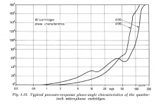
Its probably some underlying confusion on my part about the intrinsic phase response of the microphone and its acoustic-electrical delay. I read an article on measuring the acoustic center of precision microphones which only added to my confusion- apparently the center is a few MM in front of the diaphragm and moves with frequency. That leads to: the sound comes out electrically before the pressure wave arrives??. In any case it would be helpful to know the microphone phase response. The B&K curves below show the phase from an electrostatic actuator but I would like to know if it holds acoustically.
I just realized I need to update my correction files for the B&K's with the phase info, at least the generalized info in the plots.
I have long used Praxis since I know it well. It gives me complete manual control of windowing, both time and window function. But I should learn what REW can do. I would prefer to bring the signal in through REW but that may not be an option. Unless we can convince John Mulcahy to support this odd edge case.
Attachments
A pressure wave cannot begin without the movement of the earliest molecules forward. If this movement is converted to pressure by an obstruction (IE the mic capsule), then the group delay can be lower at that frequency. That's my understanding.
REW already has a lot of useful functions for this, such as time alignment. If we can specify exactly what it needs to do then I think it's worth a try.
The way I see it we need:
Recording with or without trigger output, separating the doublets into individual measurements.
Culling of doublets that are too loud or too soft, or which show interference. Spectrum-based culling would be helpful.
All measurements can be time aligned at the doublet peak and then adjusted with an offset to set absolute phase.
After the doublets are averaged together, is the time to apply windowing or DC removal.
Some of this can already be done in REW.
Hi. I gave it a try with spark generated using Cockroft-Walton Voltage Multiplier and
a Marx generator using spark gap 10mm but no special success.
I used a siglent sds1204x-e 200MHz 1 GSa/s oscilloscope to trigger on the EMP pulse
and collected data from a Gefell MV102 mic to watch N-wave length. That is 8-bit ADC
with 2ns resolution.
The problem I saw was that the N-wave did not elongate when I measured with
distances 20cm - 400cm. Wavelength was about 80uS.
When I exchanged the Marx generator with a home made capacitor (plastic & aluminium
foil) I did manage to see some elongation. If I remember correct it was
between 76uS - 82uS distance 20cm - 400cm. The capacitor broke down quite
quickly when I increased spark gap beyond 4mm.
I think I read papers that mentioned N-waves with wavelength 10-40uS (using lasers
to generate sparks). So I think I need a better spark source. Tasers not allowed for sale
in Norway. Most shops are now closed in Oslo due Covid so not easy to make better
capacitor.
I used scipy (python) to extract frequence response, but without without any
wave elongation there would be no frequency shift.
A couple of reasons:
I wanted to make sure that my spark generator really generated an N-wave.
The wavelength should elongate noticable by linear T^2 vs log(r). When I
did not see any change it must mean that the sound from spark was not a weak
shock wave? And was then the theory applicable?
Next I felt a need to confirm any results by changing the length of the N-wave.
The resulting impulse response should be stable.
- Home
- Design & Build
- Equipment & Tools
- Spark calibration of microphones