...The surface should be flat for at least a full wavelength of the lowest frequency you are interested in. For 1KHz that would be a 2' circle. ...
Your calculation is off by a magnitude.
//
For a 2 foot circle, with the spark and mic roughly together in the center, the reflected wave from the edge diffraction would have to travel about 4 feet. That is the wavelength of 282Hz.
The closest edge in my setup is about 16 inches away. That is 32 inches for the reflection to travel minus 6 inches distance from the spark to mic, which gives 24 inches until the first reflection or 1.78ms. I get 1.86ms on the measurement.
1.86ms is the wavelength of 538Hz.
Since sound waves do not travel faster than the speed of sound, nothing is happening before the reflection hits that would disturb the measurement. So in theory the first cycle of 538Hz is valid in this measurement.
However LF noise will easily introduce errors, and this EM172 is so sensitive I have to be completely still or I get subsonic noise through the floor. Not to mention noise from air conditioners running in other rooms.
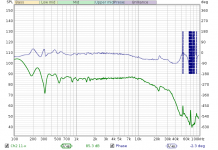
Since the taser is a louder source and less prone to spark trains, I decided to try a free air measurement. I have suspected that the ground plane measurement is still having some effect on the treble. I never get such smooth treble curves in free air measurements. Maybe the ground plane disrupts the circumferential resonance mode of the 10mm capsule.
Tuning was the same story. Reduce spark gap and get the microphone closer in order to get rid of the LF impulse.
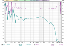
Here is the resulting response. It does bear more than a passing resemblance to the datasheet curve.
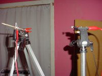
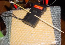
The tripod setup could stand to be improved.
It seems the coilpack is out as a spark generator. The taser always seems to give better results, although for a sensitive microphone like this it can be too loud.
Tuning was the same story. Reduce spark gap and get the microphone closer in order to get rid of the LF impulse.
Here is the resulting response. It does bear more than a passing resemblance to the datasheet curve.
The tripod setup could stand to be improved.
It seems the coilpack is out as a spark generator. The taser always seems to give better results, although for a sensitive microphone like this it can be too loud.
Attachments

Last edited:
Or, maybe not. I moved the spark further from it's tripod which was causing a reflection. I wonder if Primo's calibration setup had this variation because of their own microphone booms?
Throwing a towel over the tripod has almost no effect. Perhaps the ground plane method really will give the best results here.
Throwing a towel over the tripod has almost no effect. Perhaps the ground plane method really will give the best results here.
Attachments
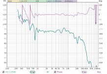
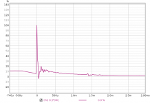
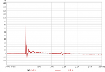
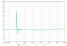
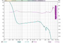
Here are some impulses derived from recorded doublets using a 200Hz lowpass filter. The electrical interference is specific to this EM172 capsule and may apply to similar capsules.
The green impulse is a fairly pristine example.
The red impulse suffers from a LF impulse, which is mostly correlated with spark length in my setup. It is coincident with the acoustic wave. It appears as a voltage shift at the impulse and then a settling afterwards. This mainly happens when the spark length is too long.
The pink impulse is an example of interference from the spark gap in addition to the LF impulse. The interference appears before the acoustic wave since electricity is faster than sound. This mainly happens when the microphone is too close to the spark or the loop area of the spark gap is too large (or one of any number of other possible EMC issues).
Attachments
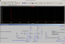
I've made a simulation which might explain the LF impulse. Overloading the internal Jfet of the electret capsule causes the internal diode or gate to conduct, which then turns off and leaves a stored charge on the gate node which slowly drains off.
Compare this to the second attachment above.
Maybe this should have been obvious, but I have not kept track of the voltage sensitivity of my computer mic input so have no baseline for overload.
Compare this to the second attachment above.
Maybe this should have been obvious, but I have not kept track of the voltage sensitivity of my computer mic input so have no baseline for overload.
Attachments
After some measurements I think to avoid overload I need to keep the capsule output voltage below 110mV peak. This would correspond to 99.8dbSPL peak. This is well below the 119dbSPL limit of the EM172. In simulation a much stronger overload is needed to create this effect, so maybe the capsule internals are different or there is overload occurring somewhere else.
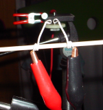
Here is the quickest way to get the best doublet.
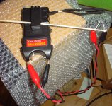
Taser connected with HV alligator clips to a spark gap on a stick. Get the taser going, hold the spark in front of you and walk toward the mic with the mic and spark gap in your line of sight.
That way you get a range of doublets and you can find the optimal distance with the best SNR.
This spark gap puts one lead closer to the mic, but it could be the polarity of that lead is less likely to cause interference. At any rate I was able to sift through doublets and find the Goldilocks Zone.
The weird thing is that I'm no longer getting the 7KHz hump in the mic response. It's disturbing just how much variation I've seen in that hump through various spark generators. Maybe I just need a good way of aiming the mic capsule.
Attachments
I should add that you may want to repeat the process multiple times to home in on a good spark length.
The taser cannot be used directly because it emits a fair amount of ultrasonic and midrange noise, and it's shape ruins the doublet response. So the alligator clips allow it to be held away from the mic.
The LF limit does not appear to be set by noise in my case. There is LF noise caused by the spark regardless of SPL or distance from the mic. Now I'm wondering if materials around the spark gap could be electrets or piezoelectric.
The area around the capsule will also influence its response. All the commercial mikes are longer tubes. Do you have a tube or even a straw to give that a try?
If I don't run into domestic pushback I'll get one of those Tasers to give it a try. Is the internal circuit published anywhere?
If I don't run into domestic pushback I'll get one of those Tasers to give it a try. Is the internal circuit published anywhere?
With the taster I am actually running into more consistency problems. It has a 20KHz noise which ramps up until spark. The noise is not really an issue for producing curves but I believe the slow ramp up of voltage is responsible for the inconsistent firing power. This is one area where the coilpack is better. But the taser is easier to use despite some inconsistency.
I didn't find a teardown of this exact taser. The case is ultrasonically welded (and/or glued, what do I know), so that may explain why.
I didn't find a teardown of this exact taser. The case is ultrasonically welded (and/or glued, what do I know), so that may explain why.
From what I can see in the battery compartment, there is a TO220, a trafo, a diode and a big 630V 330nF(?) film cap. And given I can hear a snap coming from inside the taser I am guessing the circuit is a lot like this, if not an exact copy:
http://www.next.gr/uploads/224-c480db7572.png
Explore a stun gun.
This design uses a separate potted HV trafo. The capacitor is charged via flyback and discharges into the step up trafo through a crude spark gap inside the taser. This gap may be a good place to add sphere electrodes (or perhaps just thumbtacks) to improve firing consistency.
It is probably a 2 stage design with an inverter (based on the crash course I just gave myself) and cap discharge into a second transformer for the main output. They seem to trigger the main spark when the inverter output reaches a certain level. Its all pretty crude which would explain the inconsistent output. The insides may all be potted to prevent internal breakdown. I'm looking at options that will give me a triggered spark.
I was wondering if there was a way I could get a program to automatically average several sparks to improve SNR. A reliable spark generator would go a long way toward reducing outliers in such a setup.
In the typical taser like I posted the only thing that is potted is the HV step up trafo which appears to be a very simple construction.
In the typical taser like I posted the only thing that is potted is the HV step up trafo which appears to be a very simple construction.
The software I use (Praxis) has a mode where it generates an impulse and then compares the voltage into the trasducer with what comes from the mike. I can process that impulse to trigger a spark and then use its processing which was my original interest. Unfortunately it does not support triggering from the incoming waveform.
Maybe a relay triggered to momentarily close the switch would work. Not ideal for a lot of reasons but at least something.
Maybe a relay triggered to momentarily close the switch would work. Not ideal for a lot of reasons but at least something.
The reason I went to transistor drive for the coilpack was because arcing across the contacts was causing a lot of spark trains. But the transistor drive also had the problem of switch bounce. And then you have the audible noise caused by the relay. I never ended up trying a relay for those reasons.
If you move to triggered spark you have to get the flyback generator to stop at the charging voltage so the voltage is consistent and does not drift. This would be a noise advantage if the generator is off during the doublet measurement.
A 3-terminal GDT could be used to trigger the spark on the primary side of the trafo. I've seen triggered GDTs. But then you need to drive the GDT somehow.
Perhaps a photoflash unit with the flash tube in series with the HV trafo primary? That has all the ingredients for a triggered spark.
Last edited:
It's very important that the static field produced by the spark in the vicinity of the microphone cancels out.
This is a problem with my spark on a stick. One electrode is closer to the mic. If I turn it 90 degrees so both electrodes are the same distance from the mic I get less interference.
This could be a problem with the surface discharge spark gap idea. The shell of the plug will radiate more, but if you ground the shell then your center electrode is now radiating at the mic. I suppose if the ground plane is conductive then it will be attenuated near the plane.
So, I put the EM172 in an aluminum tube. Then I put tinfoil over the front. I still got interference. If I disconnect the microphone however a dangling stereo plug picks up nothing but the 20KHz flyback noise. Presumably the static from the discharge is out of BW, but this helps rule out the preamp as a source of demodulation.
Furthermore, there is a bit less interference if one of the leads has a resistor in series with it, but not if I switch leads.
After learning about the taser internals, my new theory is that the spark gap inside the taser is causing a common mode static wave as it unbalances the circuit. This would have to be a wideband RF impulse.
So, I found an random unknown cable clamp ferrite and wound 3 turns around the microphone cable. It did not eliminate interference, but I did get some of my best doublets. It seems the capsule Jfet or a protection diode is demodulating the RF output from the taser.
So I'm not sure the spark triggered primary is the best way to make a spark generator for this. I am holding the taser and it is not grounded, so it is generating a lot of common mode noise and radiating in a dipole fashion.
I think the easiest way to get around this would be to use 2 step up trafos with the spark gap between the two primaries. I think you can get taser spark modules by themselves, so it's possible a taser could be easily modified this way. Assuming the RF behaves in a way that can be predicted.
I tried to put a ferrite clamp on the leads but it's difficult to wrap multiple turns of 20KV wire into one.
Last edited:
I found one of these and bought it DAEDALON CORP PRECISION SPARK GENERATOR EM-07 | eBay It seems to have what is necessary- 30 KV spark and a trigger input. I'll know more when mine arrives. There is virtually no documentation on the web so not sure what I'll get. Still a box with some parts would save me a lot of time.
I would think a proper electrostatic shield around the taser would reduce its radiated noise a lot.
I am planning to use some RG6 or RG 8 coax for the spark. The coax construction will minimize the radiated noise and could speed up the spark.
I would think a proper electrostatic shield around the taser would reduce its radiated noise a lot.
I am planning to use some RG6 or RG 8 coax for the spark. The coax construction will minimize the radiated noise and could speed up the spark.
- Home
- Design & Build
- Equipment & Tools
- Spark calibration of microphones