Just for the record, here is a surface discharge spark plug on Amazon:
Amazon.com : Quicksilver 97180Q NGK BUHW Surface Gap Spark Plug, 1-Pack : Sports & Outdoors
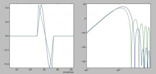
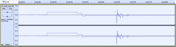
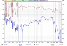
Here is the doublet traces to go with the previous charts. Red is without the Lf impulse, cerulean is with. I did note in scraping Audacity for doublets that the better ones usually had less intensity at the same time as being more symmetrical. But this is not a strict rule as some louder or less symmetrical doublets had good response.
Amazon.com : Quicksilver 97180Q NGK BUHW Surface Gap Spark Plug, 1-Pack : Sports & Outdoors
Here is the doublet traces to go with the previous charts. Red is without the Lf impulse, cerulean is with. I did note in scraping Audacity for doublets that the better ones usually had less intensity at the same time as being more symmetrical. But this is not a strict rule as some louder or less symmetrical doublets had good response.
Attachments

Last edited:
I tried another thought experiment. Take the compression half of the pulse (I found all my original data) invert and mirror it to make a perfectly symmetrical pulse, and compare it to an ideal N-wave of the same nominal length. The result seems to just add to the confusion because the real pulse looks better. The shape of the first lobe looks to hold up through a lot of experiments making me lean toward an empirical fit.
If you think it would be useful you could borrow my mic along with the cal chart. It was taken using a B&K test setup, I trust it more than the ones you find on line (unless $$$).
BTW low frequency anomalies are only made worse due to the integration in getting the impulse response. I have found time windowing that leaves a DC offset messes up things a lot.
Attachments
Last edited:
f you think it would be useful you could borrow my mic along with the cal chart. It was taken using a B&K test setup, I trust it more than the ones you find on line (unless $$$).
Any more details on the B&K test setup? Their cal process uses an electrostatic actuator. I don't think you can make that work on an ECM mike unless its of the B&K construction with the metal diaphragm. The Primo capsules have a metal grid that would make it impossible. However If there is a chance I can kludge up a test setup.
I have a stash of Panasonic WM-61A capsules. If the process is simple enough I could calibrate a handful of capsules and share. (I have both 1/4 free field and 1/4" pressure B&K capsules).
The "wizard' at Earthworks suggest that the Gefell 1/4" mike was the most accurate he has used and what he uses as a reference for his spark calibration process.
Any more details on the B&K test setup?
No they used a calibrated anechoic isolation chamber AFAIK. https://www.bksv.com/en/products/tr...ustic-accessories/anechoic-test-box-type-4232
It used to be a big egg, which appears to no longer be made. I removed all the B&K annotations from the plot. Just to be clear this is not NIST traceable reciprocity calibration.
Attachments

Last edited:
That's the hearing aid test box if its egg shaped. I see what they were doing. Its a substitution method and works pretty well if you can put the test mike in exactly the same place. The HF rolloff you show is sooner than the Panasonic's which are usually usable to 30 KHz. I'm not sure what the response of the speaker in that B&K box is.
A calibrated mic would eliminate a lot of the uncertainty, but I can't guarantee you would get any use out of my results. I basically have to construct everything out of trash, and I have very little idea how to optimize a spark generator beyond the simple setup I already have. It is also entering the time of year when turning off the AC could be a problem.
I am also very bad at following good advice. Usually I start with my own stupid ideas and then gradually resort to following someone else's example. This tends to make me look stupid, but I find it fun when I occasionally discover exceptions to some rule of thumb.
Another theory I have is that the LF impulse is related to corona discharge. Hence why non-pointed electrodes seem to perform better. Pointed electrodes will wear quickly anyway.
Yesterday I read about "spark intensifiers". They are flashy spark gaps used in series with spark plugs in a bygone era. Essentially, the extra spark gap prevents leakage through the plug fouling from preventing the build up of voltage necessary to cause a spark. If the LF impulse is related to corona discharge then perhaps pointed electrodes in series with a smooth electrode spark gap would give us a more consistent high quality doublet (without electrode horn effect). Then the problem is reducing noise from the extra spark gap. Perhaps an off the shelf GDT would be ideal here, containing the extra spark within a sealed cavity filled with inert gas. I think there are some that advertise low noise (or that is just my imagination). But then again I seem to remember something about them being degraded by weak sparks...
Last edited:
Well here is something unexpected and interesting.
Using the foam U-bend electrodes, I tried recording some more doublets. One reason I switched to the baffle experiments was this electrode started giving me inconsistent results. I was getting comb filtering starting at 10KHz.
Because of the way I stripped the ends, the connection wires broke off at the insulation, leaving very sharp points there. While testing and not getting the long sparks I expected, I noticed blue puffs coming from the broken wires. Corona discharge! The black foam makes it easy to see. I rearranged the alligator clips and it went away. And I think the comb response was due to the corona discharge behind the spark at about the wavelength of 10KHz.
I think another contributing factor may be that I've fired these electrodes so many times that perhaps their surface has worn in, becoming micro textured and changing the spark nucleation. To fix the problem of sharp points and textured surfaces, tinning with solder seems like a good idea. However I don't like the idea of vaporizing lead solder, so I don't think I'll tin at the spark.
Another thing I noticed was the sparks were feathery and I could see 2 or 3 spark trails. And then occasionally one solid, bright spark. So maybe it is actually possible to visually observe when you are getting spark trains and not single sparks.
I added a <1mm spark gap in series with the electrodes, and that did not seem to help much. Which is to be expected since the extra gap is small and pointed and the main gap is larger and smooth. The small gap therefore cannot block any significant leakage from the main gap. So my setup was built to do the exact opposite of what I wanted, but I tried anyway just out of sheer cantankerousness I guess.
However a strange side effect of the extra spark gap appears to be electrostatic interference because the gap is no longer voltage balanced. I thought that I was seeing the electrode voltage in the interference, jumping at each spark in the train, but the mic is 11 inches (814uS) from the spark and the time scales don't match up.
Attachments
Last edited:
Some observations:
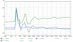
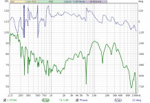
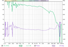
With no resistor, I get 100uS spark trains which result in 10KHz comb filtering (this was not due to corona discharge as I suspected).
With a 10ohm carbon comp resistor in series with the gap, the spark brightness is diminished and I begin to see a series of peaks and nulls in the ultrasonic spectrum. It seems the resistor lengthens the doublet period.
With a 1ohm carbon comp resistor, I get about the same spark intensity but without spark trains.
Green: no resistor
Blue: 10ohm resistor
Teal: 1ohm resistor, with mic placement changed to ground plane. (response of previous mic position is reflected in the similarities in the blue and green traces)
The ground plane mic placement is unmatched for midrange flatness and SNR, but for some reason I get a gradual downward sloping response and rolled off treble using this method.
According to this PDF, carbon comp resistors get more conductive with higher voltage. I would guess there wouldn't be much effect for a 1ohm resistor since it is the graphite particle contact regions which cause the voltage coefficient and a low ohm resistor will not have any shortage of contacts.
https://www.barthelectronics.com/pd...1 Voltage Coefficient Products_Pulse Page.pdf
Attachments

It may be the response. What is the axial relationship between spark and diaphragm? The attached chart will show you the affect of on axis to off axis for a 1/4" diameter mike (or cylinder). Your response looks a lot like the pressure response would. On axis there will be a high frequency boost. If you can, copy the correction curve and merge it with your measurement. I have pressure to on axis correction tables for 1" and 1/2" but not 1/4" yet. On quick visual inspection the mike looks pretty close to 40 KHz.
Attachments

It may be the response. What is the axial relationship between spark and diaphragm?
All the small measurement omni's I've seen come calibrated for 0 degree incidence response. I assume the curve on the EM172 data sheet is that.
I try to take measurements on axis but this was a little off, so 20KHz response is a bit worse.
I definitely don't see that trend with this EM172 mic. It rolls off at 10KHz anyway, so it would be hard to spot. It is a 10mm electret capsule.
https://www.micbooster.com/documents/EM172Z1 July 2015.pdf
The effects in your chart seem to be 2 or 3 octaves too high to be causing the response in my mic.
A 1.5db/oct filter is effective at bringing the response back to normal. When I lift the mic off the ground (mattress) by 5/8", it then needs a 3db/oct filter. I'm guessing there is some kind of absorption interaction with the reflected wave.
Using a granite tile instead of the mattress results in all sorts of issues with reflections.
EDIT: The response curves in post #68 are for the raw doublets, before lowpass conversion to impulse response. The step response traces are equivalent to the impulse response of the system.
Last edited:
I found that you really need the mike flush with the ground plane to avoid local reflections. A soft "ground plane" is not a ground plane. Again from experience.
Again the offer is open for a WM-61 to compare with. The Primo capsules are good but that one with its "grill" may not be able to get past 20 KHz.
Again the offer is open for a WM-61 to compare with. The Primo capsules are good but that one with its "grill" may not be able to get past 20 KHz.
But if it is flush then you have modified the body of the microphone for the measurement. So unless all your mics are mounted in boards what is the point?
Actually I prefer ground plane measurements of speakers where possible. By flush if its flat on the surface or really close that should be OK. The surface should be flat for at least a full wavelength of the lowest frequency you are interested in. For 1KHz that would be a 2' circle. The microphone should be less that 1/2" from the surface and pretty unobstructed in all directions.
There are measurements that you want the mike flush for, e.g. headphones.
There are measurements that you want the mike flush for, e.g. headphones.
I'm starting to get a little confused, Demian the plot in post #70 is labeled as a correction to be applied if calibration is done with an electrostatic actuator. The Earthworks write up has the Gefell data sheet with the same note. The spark test is a real acoustical event (as they say). I made a strong effort as in their article to eliminate all reflecting surfaces at the source and at the mic and got very good agreement with the direct incidence frequency response after using the correction for the N-wave nature of the acoustical output of the spark. I have no idea how Earthworks generated the 200kHz BW spark source.
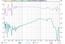
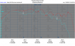
I made some on axis and off axis measurements with a Behringer type mike (Nady) and the response followed the chart quite well, below. Its an important issue when people are using these instruments incorrectly and then making judgements from them.
The Earthworks claims are pretty questionable if they say 200 KHz. However the microophones are only good to 50 KHz, which is consistant with the WM-61's they were using when they started. They seem to have something about their spark generator and gap acoustics. B&K says you MUST remove the grid to get close to 100 KHz because there are resonances behind it around 100 KHz. Also how can you verify 200 KHz? Maybe with a 1/8" mike. I had one but it was defective and B&K wanted $2K to repair it.
I wonder if some type of pressure tube or similar resonant device could be used to make a short acoustic pulse. I did read about explosive charges used however you are still without a solid fundamental basis for accuracy. Only levered against a calibrated mike.
Attachments
The Earthworks claims are pretty questionable if they say 200 KHz.
No they were verifying their test setup with the Gefell and B&K mics not claiming that their mic was >50kHz. The plots are very clean with the Gefell flat to just under 150kHz. They unfortunately give no details or theory showing what they did differently. They reprinted the FR plots of both and they show the same things you showed, but I thought the 0 degree incidence plot is what is expected using a spark to generate an acoustic plane wave. They do mention that the mic should have no protuberances or abrupt changes in the shape of the body and all booms etc. should be padded.
Maybe we are talking about two different things I was interested in the mic cal not measuring headphones or speakers with it.
Last edited:
I'm trying to catch up on this, but just checking. Are you trying to use std auto coilpacks for this? I would, from my days experimenting with this use the CD pack off a mower or strimmer. lower power spark and much shorter. inductive discharge ignition will be hard to get symmetical.
I have a very sad collection of ignition parts in my shed...
I have a very sad collection of ignition parts in my shed...
I have several interests here. First microphones need to be used in concert with its application. For a loudspeaker you want free field calibration since that is how you will use it. For headphone testing in an artificial ear type application you need a pressure calibration and you mount the mike flush with the surface. I deal with both and have been collecting these mikes for decades. Fortunately the B&K mikes are stable for decades. Sill I need to verify calibration and that where the spark became interesting. If a spark was a "perfect" impulse it would be great for a predictable response but it seems sparks are no more predictable than other transducers and will be impacted by all aspects the the gap and the discharge. I can do an electrostatic cal of the 1" and 1/2" mikes but not the 1/4" mikes. Fortunately I have a pretty current calibration of one of the 1/4" mikes but no transducer good to 100 KHz to transfer with to the other mike.
This is all more of the pointless pursuit of perfection than something of immediate use.
This is all more of the pointless pursuit of perfection than something of immediate use.
- Home
- Design & Build
- Equipment & Tools
- Spark calibration of microphones