I'm trying to catch up on this, but just checking. Are you trying to use std auto coilpacks for this? I would, from my days experimenting with this use the CD pack off a mower or strimmer. lower power spark and much shorter. inductive discharge ignition will be hard to get symmetical.
I am using a cheap chinese Ford V6 coilpack which caused me a 30% loss in MPG, and I can't get longer than a 9mm spark, so may be more suited for this. Real Motorcraft OEM coilpacks are known to be very strong.
Since you indicate you've tried this, what is the important factor for symmetry in the waveform? This indicates to me that the inductive source impedance wants to keep the spark on too long.
Also note that I am not using spark plug wires which are highly resistive, just alligator clips. Just a 10ohm resistor in series with the spark gap was enough to create a repeating null in the measurement but 1ohm was just right to prevent spark trains.
Last edited:
This is all more of the pointless pursuit of perfection than something of immediate use.
Well the idea is that we could come up with a DIY formula and then it would be immediately useful. You say this but then I'm not sure why you are commenting at all???
Why are you interested in surface discharge spark plugs if it is not useful???
I am certainly interested in borrowing a calibrated mic and am thankful for the offers, but I want to figure how how I will be using them before I commit. I know you have criticisms of my methods and I fully expect to be doing this wrong, but I am also trying to explore possibilities.
Frankly, I think the mattress plane measurements look like a good way to start if some correction factor can be figured out given the results. Maybe migrate to towel plane measurements to make it more portable. Fiberglass plane?

Since you indicate you've tried this, what is the important factor for symmetry in the waveform? This indicates to me that the inductive source impedance wants to keep the spark on too long.
.
I've not tried what you are doing but I did play around tuning up engines that need a big spark. So I have an inkling of what NOT to do. Basically inductive discharge ignition is all focussed about getting as much energy into the spark kernel to light the fuel mixture. So you saturate the coil as much as you dare then let LdI/dt do its magic. 5-7A charging current was used in distributor days. If you just want rise time this might be fine, but you'll never get the same decay twice.
Capacitive discharge (CDI)* was mainly used on little engines that didn't have an alternator and drag strip setup (MSD) until SAAB starting using it in the 80s for their turbo engines. They wanted to measure the Ion currents during combustion to check for impending knock as well as combustion efficiency. Clever stuff slurped into Delphi when GM ate SAAB. Anyway to be able to do this the spark has to be a very short duration, so CDI was used.
I would guess with whatever coil you have lying around charging a cap to 200V and dumping it into the coil primary should give you the sort of spark you want.
*I did a history delve on this and apppears some magneto systems did have capacitive storage 100+ years ago. So nothing new under the sun. And I have a pile of articles to read on old engine tech, which is fun 🙂
Okay, I think we are talking about different things.
My waveform will always be asymmetrical because the mic has a lowpass characteristic which turns a doublet into an impulse. So the recording is something in between a doublet and an impulse. I don't think this is what you meant by symmetry.
I suspect a lot of variation in my setup is coming from the 2 9V batteries in series with a 22000uF capacitor in parallel. The coil primary is 0.5 ohms so 0.5*22000uF=11mS time constant. I trigger with thumbtacks pounded into the back of a clothespin so whether the release occurs 11mS after the contact will be hit or miss. It fires on contact, release or both depending on battery voltage, trigger resistor, gap length, gap points, and whether it feels like it. But with good tuning I can get a fairly consistent doublet shape despite the variation of amplitude.
Considering this maybe I can get a more consistent spark by charging the 22000uF cap with the batteries through a 1k or so resistor and then discharging the cap into the primary. I think this will work since the coil doesn't seem to rely on flyback effect to fire.
Ah ok, you basically have built a CDI setup and are using the coil as a transformer. Yes that is the way.
Edit: looked at the pics. You 'might' get some improvent on a better spark gap. You really want two sharp points so you know the spark will always go roughly the same way.
Edit: looked at the pics. You 'might' get some improvent on a better spark gap. You really want two sharp points so you know the spark will always go roughly the same way.
Last edited:
Okay, rate this ground plane.
Pretty good. I do not have a sense of the scale. And there may be a reflection from the C Clamp but you should be able to see that on the impulse waveform at the appropriate time/distance. You should then be able to window that out and focus on only the free space time. It will behave as a free space because there are no local reflections. Yo can actually raise the spark off the surface to get a sense of directionality.
Do you know what voltage you are getting for the arc? its always confusing to look at peak voltage and peak current. On the surge generator it was 6KV at 3KA which translates to 18 Megawatts. However that only present for a brief instant. (BIG noise when you do arc.)
My point above was that this is interesting and potentially useful but not something I need working now to do something else. Much like oscillators with -160 dB distortion or clocks accurate to parts per trillion.
I'll be happy to help as I can. Something easily reproducible would be a very valid goal and could be used by many. Maybe not +/- .1dB but even repeatable to +/1 2 dB at the top would be great. The surface gap sparkplug would work well with a ground plane minimizing any local cavities or resonances.
but even repeatable to +/1 2 dB at the top would be great.
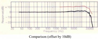
I already did that years ago, 20kHz is all I needed YMMV.
Attachments
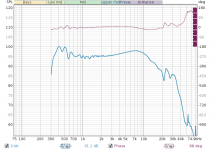
The spark is about 14.5 inches from both edges. 1 inch is 74us so the edges are 1.073ms away.
I have REW set up to do a 15 cycle window. This means that for 10KHz, the window is 1.5ms (750uS before and after) and for 1KHz, it is 15ms and so on. This gives more accurate LF information than a fixed window, while excluding reflections at HF according to a fixed octave resolution.
I have REW set up to do a 15 cycle window. This means that for 10KHz, the window is 1.5ms (750uS before and after) and for 1KHz, it is 15ms and so on. This gives more accurate LF information than a fixed window, while excluding reflections at HF according to a fixed octave resolution.
Edit: looked at the pics. You 'might' get some improvent on a better spark gap. You really want two sharp points so you know the spark will always go roughly the same way.
I've tried the sharp points thing. From my experience, that is not the way.
1: Sharp points have a less consistent spark voltage and arc path
2: Sharp points prevent voltage buildup due to leakage from corona discharge
3: Sharp points wear quickly
4: Sharp points fire more easily, encouraging spark trains. Corona discharge is also audible, so they may interfere even if there is no repeating spark.
On the first page, someone posted information on spherical electrodes and spark consistency. My electrodes are just bent wires which are smooth and don't have sharp corona-causing features. They are not large enough to have the benefits of spherical electrodes, but the required sphere size to gap ratio is so large it would interfere with the shockwave and create a horn effect.
Therefore I think the side wire electrode is a pretty good compromise of desirable properties.
I suppose that is fair, you already did it years ago so all this must seem pretty pointless. Maybe I try too hard to use what I already have laying around.
Edit: looked at the pics. You 'might' get some improvent on a better spark gap. You really want two sharp points so you know the spark will always go roughly the same way.
Are you saying the arc will be straighter with sharp points? I could be wrong on this, and probably everything else too. But I seem to be getting better results in general without points. At small gap sizes like this I don't think the arc needs to be any straighter for <20KHz.
Might also be easy to set it to repeat with a zener?
One thing that makes me nervous is how different spark sources seem to give different results. I've used a taser, a stove lighter and now an ignition coil. It's difficult to get them to agree.
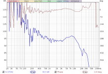
Here is a taser with the ground plane (now it's a baffle I guess) spark but with the mic 3 foot 9 inches away on a tripod to get the loudness low enough for the mic.
Unlike the ignition coil sparks, there definitely seems to be repeating nulls in this measurement which fits with the research that higher power sparks have less BW. But really I'm not sure the the taser is powerful enough that the BW limit should encroach on audio frequencies.
The window here is set to 1ms, which is one inch shorter than the distance to the baffle edges.
One thing that makes me nervous is how different spark sources seem to give different results. I've used a taser, a stove lighter and now an ignition coil. It's difficult to get them to agree.
Here is a taser with the ground plane (now it's a baffle I guess) spark but with the mic 3 foot 9 inches away on a tripod to get the loudness low enough for the mic.
Unlike the ignition coil sparks, there definitely seems to be repeating nulls in this measurement which fits with the research that higher power sparks have less BW. But really I'm not sure the the taser is powerful enough that the BW limit should encroach on audio frequencies.
The window here is set to 1ms, which is one inch shorter than the distance to the baffle edges.
Attachments

Thinking the comb filtering may be due to a spark train, I added a second spark gap at the taser. However the spark from the other gap came back clean and the one on the baffle did not. So this is clearly an acoustic problem.
I switched to smaller alligator clips and positioned them more radially and that made a big difference. I already made the same change on the ground plane version of the measurement without results. I think this is just because in the ground plane measurements the clips were not positioned where their reflections would hit the microphone.
One thing I find often is that you may have a potential reflective surface, but if it is oriented well it's reflection doesn't hit the mic and it has minimal impact on the measurement.
Oddly with the taser, I can use my thick insulated alligator clips in twisted pair whereas for the ignition coil I could not because it would not spark. I'm not really sure why. The clips are silicone insulated rated for 20KV.
When I started with the ground plane setup and the taser, I had a significant LF impulse ruining the response. The length of the gap affects the LF impulse disproportionately. The mic distance has a slight effect in comparison. I suspect that the LF impulse is related to SPL overload as it is coincident with the acoustic wave, and increasing mic gain in the computer doesn't improve it. Therefore the spark length matters most because increasing the gap increases both joule energy and the acoustic efficiency of the spark.
S as I reduce the gap length and move the mic closer and closer, the LF impulse diminishes and the curve is accurate to lower and lower frequencies. The mic is about 5.5" away and the gap is <1mm. Since the taser has more energy, it needs a smaller gap to match the coilpack.
When the mic is this close however I run into another issue. Electrical interference shifts the signal before the acoustic wave hits, at the moment the spark fires. I was using my smaller alligator clips as they make less reflections, but they are magnetic steel. I switched to my larger alligator clips which are copper and also twisted pair, and this interference mostly went away. So it could be magnetic noise or it could be related to something else I shifted when doing this. Maybe even antenna geometry of the leads.
So the obvious step forward would be to finally ditch the alligator clips.
I've screwed around enough so far I think it is about time to home in on a setup that is most likely to give good results. My thoughts on what this would be:
1: Ground plane measurement. This increases SNR and reduces the possible reflections. An entire wall could be used for excellent results.
2: Wire electrodes without sharp edges, firing from the sides of the wire. Taped flush with the plane.
3: HV twisted pair to supply the spark gap. 20KV wires have been fine for me. LV wires aren't good enough because you have to space them apart and this increases interference from the huge arc current. The better you can make this the closer you can put the mic.
4: Taser source. No spark trains, and a wide range of usable gap lengths. Automatic repetition at a good interval. Adjusting the gap length is a very good way to optimize SPL for the best SNR, although ultrasonics may come into question with longer lengths. This is the one I have: Amazon.com : Dragon Fire Stun Gun - 100, 000 Volts : Other Products : Everything Else
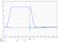
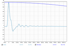
Here is a test. Response, window, impulse, and then doublet.
S as I reduce the gap length and move the mic closer and closer, the LF impulse diminishes and the curve is accurate to lower and lower frequencies. The mic is about 5.5" away and the gap is <1mm. Since the taser has more energy, it needs a smaller gap to match the coilpack.
When the mic is this close however I run into another issue. Electrical interference shifts the signal before the acoustic wave hits, at the moment the spark fires. I was using my smaller alligator clips as they make less reflections, but they are magnetic steel. I switched to my larger alligator clips which are copper and also twisted pair, and this interference mostly went away. So it could be magnetic noise or it could be related to something else I shifted when doing this. Maybe even antenna geometry of the leads.
So the obvious step forward would be to finally ditch the alligator clips.
I've screwed around enough so far I think it is about time to home in on a setup that is most likely to give good results. My thoughts on what this would be:
1: Ground plane measurement. This increases SNR and reduces the possible reflections. An entire wall could be used for excellent results.
2: Wire electrodes without sharp edges, firing from the sides of the wire. Taped flush with the plane.
3: HV twisted pair to supply the spark gap. 20KV wires have been fine for me. LV wires aren't good enough because you have to space them apart and this increases interference from the huge arc current. The better you can make this the closer you can put the mic.
4: Taser source. No spark trains, and a wide range of usable gap lengths. Automatic repetition at a good interval. Adjusting the gap length is a very good way to optimize SPL for the best SNR, although ultrasonics may come into question with longer lengths. This is the one I have: Amazon.com : Dragon Fire Stun Gun - 100, 000 Volts : Other Products : Everything Else
Here is a test. Response, window, impulse, and then doublet.
Attachments

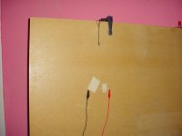
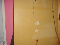
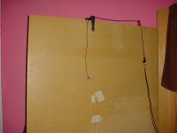
Photos.
Some things I would improve about this setup:
1: The wires are spaced apart to prevent arcing before the gap. Ideally these wires would be like the 20KV wires on the alligator clips, and twisted together in the same way to reduce interference from the huge spark current. I don't want to destroy my alligator clips to do that though.
2: The tape is a bit sloppy, creating some resonant cavities in theory.
3: The mic is not exactly parallel with the spark, but maybe not so important for a <1mm spark under 20KHz.
Attachments

- Home
- Design & Build
- Equipment & Tools
- Spark calibration of microphones