After looking in vain for CDI circuits involving avalanche diodes it seems that using a diode in this way is actually a rare thing. Avalanche generally just means reverse breakdown and all avalanche diodes probably don't behave like this. Or do they? I just don't know. I did not get any of my diodes to fire. Maybe they just need a higher breakdown current before they will fire.
This paper shows an FUF4007 doing it at 1400V and 0.95A. My circuit probably can't supply 0.95A. Maybe the K1V22 is special in being able to fire at a lower breakover current.
https://www.fagorelectronica.com/images/download/semiconductor/Fagor-Avalanche-Rectifiers.pdf
This paper shows an FUF4007 doing it at 1400V and 0.95A. My circuit probably can't supply 0.95A. Maybe the K1V22 is special in being able to fire at a lower breakover current.
https://www.fagorelectronica.com/images/download/semiconductor/Fagor-Avalanche-Rectifiers.pdf
Last edited:
I'm still trying to understand how the avalanche diode works in that circuit. They are similar to centers and would clamp the peak voltage across. I can see it shunting the peak reverse current as the coil discharges. I don't see what triggers the discharge.
Maybe a gas tube in series would work to trigger. HV on one side arc with large resistor on the other. When the breakdown voltage for the tube hits the tube shorts discharging through the spark gap? There are special tubes for this (Krytron).
Maybe a gas tube in series would work to trigger. HV on one side arc with large resistor on the other. When the breakdown voltage for the tube hits the tube shorts discharging through the spark gap? There are special tubes for this (Krytron).
I presume you are talking about GDTs. These GDTs seem characterized for CDI circuits (I guess maybe they all are):
https://www.unsemi.com.tw/upfile/file/20180614/2018061411461965447.pdf
There are triggered GDTs. Photoflash circuits often have a tiny HV trafo just to send the triggering pulse to the flash bulb. I have a few I could try if I can figure out how not to fry them.
I figured the K1V22 diode was operating in avalanche based on it's reverse voltage and the DMM gave 0.5V across it in the forward direction shown in the schematic even though the markings were in the wrong direction. It wouldn't make sense for it to work any other way as far as I can tell. Even if I traced the transformer wrong and the output winding was grounded, the capacitor would not be able to charge as the K1V22 would shunt it. The ignition trafo doesn't have something hidden in the windings because the primary measures like a short.
My understanding is that at some point beyond the breakover voltage the avalanche diode has negative resistance and so you need to be able to reach that point without it's leakage current limiting the charger voltage. And this would require a survey of diodes to find one that is compatible.
I did not see references to negative resistance in the lit. Tunnel diodes yes. I would think the power dissipation would be enormous at those voltage/ current numbers. I have explored the abrupt zero resistance mode for diodes but that usually requires a soldering iron to reset.
In the PDF in post #221, it shows what happens when a diode enters the negative resistance mode with an inductive load.
Avalanche diodes are rated at typically something like 20mJ avalanche energy, so as long as the pulse is short it's fine.
Also, I am an idiot. The K1V22 is not a diode, but a SIDAC, and has a listing on Mouser:
K1V22(W) Datasheet PDF Viewer. - Datasheet.Directory
There are plenty of other SIDACs that might work fine in this application.
I looked at previous spark measurements, and the Olympian sparker has only a little less 20KHz rolloff than the taser. The heavy rolloff seems to have always been in the measurements since I stopped using the ground plane, but the roughness in the curves helped hide it. Now with the better acoustic setup it is rather obvious. It is puzzling me. The datasheet certainly doesn't show this trend.
Now here is a theory. As the doublet elongates the allpass characteristic increases because the LF lag more and more behind the HF. So what is the chance that we could infer the doublet BW from the allpass phase value? Only issue is how well the microphone obeys minimum phase. Since it is allpass, it may be evident where the microphone's response is pistonic. So how do we get from a 5 degree allpass phase to the corner frequency of the doublet?
One of these might replace the spark gap in the taser, although I'm not sure what the taser pulse is like or if it fits in the ratings:
https://www.mouser.com/datasheet/2/240/IXBOD1-1549167.pdf
Other than that, the K1V22 and most of the other SIDACs have 100ohms minimum dynamic resistance, so I don't think they would replicate a spark gap. That might not necessarily be a bad thing.
I managed to get an allpass filter working in Python. It works on phase, but it doesn't shift the group delay at all. I need a frequency dependent group delay to counteract the delay of the doublet.
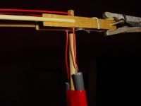
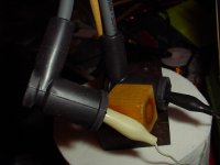
I got a set of spark plug wires and used them with the frankentaser. The most obvious effect of the spark plug wires is that everything before the wires experiences much more transient voltage. The taser points want to fire. They will show corona or sometimes fully fire. To help with this I did something that should not have worked but worked anyway. I took a section of spark plug wire, drilled out the conductor and then connected it between the taser points like a bent tube. I expected the residue of the carbon conductor to encourage the points to fire, but that does not seem to be the case.
See, if I was a real engineer I would never have tried that. I actually got a surprisingly tight spark group from that run.
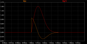
As far as the effect on the doublet, there is an oddly well defined step right after the impulse. It makes sense to me that the wires may lengthen the glow discharge period if it is affecting the doublet, but that is only a theory as to why this is happening.
See, if I was a real engineer I would never have tried that. I actually got a surprisingly tight spark group from that run.
As far as the effect on the doublet, there is an oddly well defined step right after the impulse. It makes sense to me that the wires may lengthen the glow discharge period if it is affecting the doublet, but that is only a theory as to why this is happening.
Attachments
Primo has come out with the EM419 which is the replacement for the EM258. Looks like it uses a new capsule but different Jfet. SNR and max SPL are 1db better, but I have to wonder if this is not just so that customers will happily accept the replacement. EM258 and EM419 datasheets:
http://micbooster.com/datasheets/EM258.pdf
https://www.primocorp.co.jp/product-corp/fileview/49/EM419NM1
It's interesting that they have added a LF spec. +-10 degrees at 30Hz.
The EM419N and EM419NM1 are a bit different with the EM419N having a higher max SPL.
http://micbooster.com/datasheets/EM258.pdf
https://www.primocorp.co.jp/product-corp/fileview/49/EM419NM1
It's interesting that they have added a LF spec. +-10 degrees at 30Hz.
The EM419N and EM419NM1 are a bit different with the EM419N having a higher max SPL.
Last edited:
The phase spec relates to using them in ANC applications. (I'm immediately changing a spec once this email is out.) Particularly in ANC feedback you have enough problems with drivers. Having variations in the mikes at low frequencies where there is lots of feedback is not good. It also means a small pressure balance port. All good.
When testing both the EM272 and the EM258, they both have pretty much the same rolloff at 20KHz. But the EM272 tests roughly on-spec whereas the EM258 should be pretty flat to 20KHz.
So either the EM272 performs better than spec or the EM258 performs worse. Which is it?
https://www.primocorp.co.jp/product-corp/fileview/11/EM272.pdf
http://micbooster.com/datasheets/EM258.pdf
So either the EM272 performs better than spec or the EM258 performs worse. Which is it?
https://www.primocorp.co.jp/product-corp/fileview/11/EM272.pdf
http://micbooster.com/datasheets/EM258.pdf
Attachments
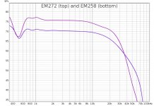
I did wonder if Primo tested their mics with a grommet or in a baffle of some sort. It would be nice to know if that is the case. Realistically the roughness in the curves must come from somewhere.
I found a comparison of the EM258 with the ECM999 on a German forum.
* Binaurale Wiedergabe über Kopfhörer., Reviews und lesenswerte KH-Themen - HIFI-FORUM (Seite 8)
This measurement shows the EM258 as having 6db extra sensitivity at 20KHz, not less. You are in the twilight zone.
I found a comparison of the EM258 with the ECM999 on a German forum.
* Binaurale Wiedergabe über Kopfhörer., Reviews und lesenswerte KH-Themen - HIFI-FORUM (Seite 8)
This measurement shows the EM258 as having 6db extra sensitivity at 20KHz, not less. You are in the twilight zone.
German forum said:Figure 3: Green Superlux ECM999, red Primo EM258 right, blue Primo EM258 left. Distance about 50-60cm from the speaker. The Primo capsules were about +-2cm away from the Superlux and placed about 3-4cm higher than the Superlux ECM999. The angle was somewhere between 3-10° for the capsules and 0° for the Superlux. The curves were pushed on each other by eye. I find the frequency response of the capsules to be very similar. Up to 6KHz there is hardly any difference to the Superlux ECM999. After that, there is a treble emphasis. For Impulcifer, however, you could actually use the capsules for room correction, since you actually only need the room influence range <1KkHz.
Translated with www.DeepL.com/Translator (free version)
Attachments

So glad you decided to fit some spark plug wire! As much as I love alligator clips -- and use them extensively myself -- seeing your jumpers, even though only lightly twisted, with their 600 or 1kV insulation had me worrying for you.
This is some really great work you're doing. 😀
(Following closely -- but not closely enough to get this posted before 4 other posts! 😱 )
Regards
This is some really great work you're doing. 😀
(Following closely -- but not closely enough to get this posted before 4 other posts! 😱 )
Regards
Last edited:
Thanks for the encouragement! But the spark plug wires don't make me feel the least bit safer. I just keep well clear of the output side of the circuit. The bit that the wires insulate is the least interesting section of the circuit, and the increased voltage before the wires (due to their high resistance) actually makes it more dangerous (but no more dangerous than a taser is normally).
My thick alligator jumpers use silcone wire rated for 20KVDC, although the fast risetime makes them more susceptible to puncture.
My thick alligator jumpers use silcone wire rated for 20KVDC, although the fast risetime makes them more susceptible to puncture.
Attachments
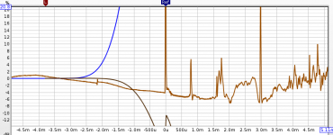
I figured out how to synthesize a more realistic spark doublet in LTspice using a nonlinear capacitor. This model gives -3db at 20KHz when set to a similar frequency dispersion pattern. But there is no allpass characteristic in the spectrum so that may have been a red herring.
Attachments
Both the spark and the capsule body itself can have the effect of moving the HF earlier in time due to the acoustic center moving forward as the wavelength approaches the capsule size (correct me if I'm wrong). So it's not obvious that the two can be told apart.
So glad you decided to fit some spark plug wire!
The reason for the spark plug wires was actually to see if it would work better than ferrite beads at reducing interference. The wires have a carbon conductor with about 11kohms per wire. What I realize now is that because the spark can't limit the voltage at the beginning of the spark plug wires, the E-field from the spark event actually increases, increasing interference.
And as for the response, it doesn't seem to be any different when using the spark plug wires. I had hoped for some meaningful change but they don't seem to do much.
- Home
- Design & Build
- Equipment & Tools
- Spark calibration of microphones