Don't know if it's still available, but there used to be ignition wire with tinned copper conductors. The muscle car guys (1970's) were just sure it gave 'em a few extra horsepower.
The 50kV insulation should lower the coil's load capacitance. But if your alligators are 20kV silicone insulated, it probably wouldn't be much of an improvement. Just a thought.
Regards
The 50kV insulation should lower the coil's load capacitance. But if your alligators are 20kV silicone insulated, it probably wouldn't be much of an improvement. Just a thought.
Regards
Last edited:
Yes, the lower capacitance was one reason I wanted to try the spark plug wires, specifically with the Olympian sparker which is sensitive to insulation and/or capacitance. But now I see that it will probably have arcing problems because of the resistance, and it doesn't seem to need it anyway. Furthermore it will probably increase interference rather than reduce it like I thought. Still worth a try though I guess.
I hooked up the Olympian sparker to the spark plug wires. Oddly enough the spark plug wires still seem to benefit from the powered iron ferrites before the spark gap.
As I expected it is hard to get it to fire with the spark plug wires. This is because the Olympian is a lower voltage version of the taser with a faster risetime. The spark length is limited.
The goldilocks zone between too much noise and too much interference is small. The Olympian already causes extra interference due to the risetime, but now the E-field is increased due to the spark plug wires. I had to trigger with a relay to eliminate the trigger wires as a radiator.
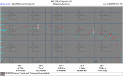
Oddly enough the 20KHz rolloff has been reduced by 1 or 2 decibels. I saw this comparison of various measurement microphones with the Earthworks QTC-1 and the Earthworks consistently had lower output at treble. So maybe other calibration methods tend to emphasize treble? And the drop I see could be the actual response?
RealTraps - Measuring Microphones
As I expected it is hard to get it to fire with the spark plug wires. This is because the Olympian is a lower voltage version of the taser with a faster risetime. The spark length is limited.
The goldilocks zone between too much noise and too much interference is small. The Olympian already causes extra interference due to the risetime, but now the E-field is increased due to the spark plug wires. I had to trigger with a relay to eliminate the trigger wires as a radiator.
Oddly enough the 20KHz rolloff has been reduced by 1 or 2 decibels. I saw this comparison of various measurement microphones with the Earthworks QTC-1 and the Earthworks consistently had lower output at treble. So maybe other calibration methods tend to emphasize treble? And the drop I see could be the actual response?
RealTraps - Measuring Microphones
There were several aspect of that test that I found odd. The gefell is calibrated on axis so measuring at 90 degrees like they did with all the mikes would have a different response. The 1/2" mikes will have an 8 dB difference on axis to 90 degrees. The 1/4" mikes are around 4 dB. It all makes your head spin.
Then you need to sort out pressure vs free field. Most of the electrets are free field calibrated and would typically work past 20 KHz.
Below is a comparison of my B&K 4135 and the Panasonic ECM that came with Praxis many years ago. The source is a Pioneer ribbon tweeter that hits a wall at 35 KHz. Its easy to see why I use the ECM for most tasks. The wiggles are typical of real world measurements. The tweeter is useable above 35 KHz but not easily. I think there are aspects of its physical size that limit it. And I would need to remove the screen on the B&K, something I only do when absolutely necessary.
Attachments
I'm not sure what to do next. Everything is sort of at a standstill because I have no reference.
I suppose if I want to replicate Earthworks' results, then the best option would be to get an Earthworks mic or Gefell. But that's not going to happen.
To be fair, if the orientation isn't marked on the microphone or at least in the case somewhere I would probably make the same mistake. The present education may rectify that though.
I set my script to measure the offset 100uS before the spark and subtract it from the recording. This seems to help a lot in reducing spectral leakage from windowing, and extends the usable LF response.
Being close to the spark is a significant advantage when it comes to reflections. The distance between the mic and spark directly subtracts from the distance to the nearest reflection, so you get the best results when the mic is close to the spark. For me to get valid data near 1KHz I must keep them close.
This trial was done with the mic about 18" from the spark, using the taser with alligator clips.
Attachments

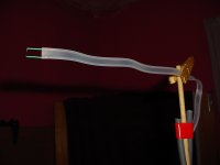
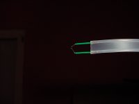
I just got some 300 ohm twin-lead I wanted to try. It seems ideal in several ways. The conductors are spaced well enough for most usable gap sizes. It has very little capacitance. It is acoustically unobstructive in the right orientation and is self-supporting which helps minimize any scaffolding around the spark.
I didn't find any rigid types of this cable for sale but that would be even better.
It seems to perform well in terms of spark consistency. But I get the LF anomaly again, and now it shows up as an odd tail on the impulse response. The effect is the same with and without the alligator clips feeding the twin lead.
The electrodes are tinned copper breadboard links with sharp cut edges, so maybe that has some effect. Perhaps the sharp edges allow the arc to continue longer than necessary. I have been using silver plated copper for electrodes so far.
Attachments
Compare that to this impulse response I get after curving the electrode so they don't fire from the points.
But actually the LF anomaly is present in both. The electrodes may have had a tiny effect but I don't see much difference.
But actually the LF anomaly is present in both. The electrodes may have had a tiny effect but I don't see much difference.
Attachments
Overall interference is the largest issue with the twin lead, having not added ferrites yet since it will take some cutting. After adding ferrites it will be more of a fair comparison with the other cables. The endgame with the twin lead is to try it with the Olympian which really dislikes capacitance. But I am not optimistic due to trends with interference.
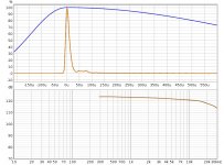
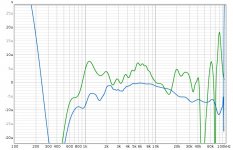
This chart illustrates that this is not a good position to be in, since I can pretty much tweak the setup until I get the curves I think I should be getting, irrespective of reality. The orange and green are the runs from the last 2 posts. The blue response is from moving the mic closer to a much smaller gap, and the red response is after adding a ferrite cable clamp to the twin lead at the base of the dowel.
The blue and red responses dip in the midrange because of interference that happens before the acoustic wave hits. The ferrite clamp reduces this interference so the red curve is less severe, but slight interference can still be seen on the impulse response.
EDIT: looking at the again I see that the the impulse response tails are lifted for the upper traces and dip for the lower traces and this matches the responses better than the interference. So it seems in this case the LF anomaly is coincident with the acoustic wave. This is puzzling but I can try moving the mic further away.
Attachments
Last edited:
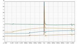
Suspecting acoustic overload, I moved the mic about 1.5x further away, but the results are pretty much the same. So I think the LF anomaly in this case was classic acoustic overload, and this result is pretty good when it comes to doublets.
The red trace is from the last post and the purple trace is with the mic moved away. You can see the distance between the E-field blip and the acoustic wave has increased.
The red trace is from the last post and the purple trace is with the mic moved away. You can see the distance between the E-field blip and the acoustic wave has increased.
Attachments
I tried using the Olympian with the twin lead. The only method which really worked to reduce the interference was to use sharp points on the electrodes. This eliminated intermittent loud sparks which would cause a lot of interference.
Now for some reason 20KHz is 8db down, and neither distance nor gap length affects it.
I made the gap very small using sharp electrodes and moved the microphone closer. I found a small improvement by adding a 100ohm resistor across the primary. Then I tried 68ohm, 10 and 6.8ohm carbon comp resistors.
It looks like the low-capacitance twin lead allows the transformer ringing to keep the spark alive for too long, where as some capacitance or resistance previously attenuated the ringing.
I found that a combination of a diode and a damping resistor on either the primary or secondary gave the best results.
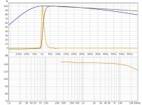
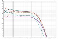
From top to bottom the impulse response shows
100ohm primary shunt resistor
10ohm primary shunt resistor
BYM26C primary shunt diode
BYM26C // 10ohm primary shunt
BYM26C primary shunt + 220kohm secondary shunt resistor
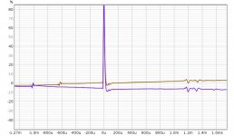
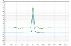
The blip before the impulse is the E-field from the spark event which shows the damping or ringing of the transformer. You can see the distance from spark to microphone decreases over time as the tripod settles, but this is not significant.
For the last test the mic was 2.5" from the spark. The pointed electrodes as well as reducing radiating surface area reduced interference quite a lot. This is important because with damping, the spark would not fire loud enough to get good results with a lot of distance. Furthermore having the spark close to the mic maximizes distance to reflections as well as minimizing the intensity of the reflections, so has a very powerful advantage.
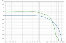
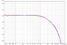
The resulting response seems very close to the datasheet in the last attachment.
The transformer rings with a period of 20uS, so I think this will affect the BW limitation of the calibration. I was not able to find an inductor to use in parallel with the primary which would decrease this time constant and still fire a spark. That leaves reducing the capacitance as an option, if it will still fire a spark.
Now for some reason 20KHz is 8db down, and neither distance nor gap length affects it.
I made the gap very small using sharp electrodes and moved the microphone closer. I found a small improvement by adding a 100ohm resistor across the primary. Then I tried 68ohm, 10 and 6.8ohm carbon comp resistors.
It looks like the low-capacitance twin lead allows the transformer ringing to keep the spark alive for too long, where as some capacitance or resistance previously attenuated the ringing.
I found that a combination of a diode and a damping resistor on either the primary or secondary gave the best results.
From top to bottom the impulse response shows
100ohm primary shunt resistor
10ohm primary shunt resistor
BYM26C primary shunt diode
BYM26C // 10ohm primary shunt
BYM26C primary shunt + 220kohm secondary shunt resistor
The blip before the impulse is the E-field from the spark event which shows the damping or ringing of the transformer. You can see the distance from spark to microphone decreases over time as the tripod settles, but this is not significant.
For the last test the mic was 2.5" from the spark. The pointed electrodes as well as reducing radiating surface area reduced interference quite a lot. This is important because with damping, the spark would not fire loud enough to get good results with a lot of distance. Furthermore having the spark close to the mic maximizes distance to reflections as well as minimizing the intensity of the reflections, so has a very powerful advantage.
The resulting response seems very close to the datasheet in the last attachment.
The transformer rings with a period of 20uS, so I think this will affect the BW limitation of the calibration. I was not able to find an inductor to use in parallel with the primary which would decrease this time constant and still fire a spark. That leaves reducing the capacitance as an option, if it will still fire a spark.
Attachments


Last edited:
It seems I am working out how to get the whole system working. It is a long list of things that need to be done right, and any single one can ruin the results.
The impulse centering and averaging has extended the usable LF BW to the point where room reflections become the confounder, and the spark trafo damping has restored usable HF response. Use of gratuitous ferrite beads and triggering through a relay for isolation minimizes interference so the mic can be close to the spark. Having the mic close to the spark maximizes reflection distances and minimizes their intensity. Minimal scaffolding leads to a very clean impulse decay.
So here is where I am at with the EM272 and EM258. Some interference is still visible on the EM272 impulse but it has been windowed out.
Attachments
I have been on the road but I'm back home. I can set up a calibration of a mike or two and send them over for you as references if you want. I have a handful of possible candidates.
I would really like to have an "intrinsically" predictable way to check mike response. It would be a great cross check of what I have.
I would really like to have an "intrinsically" predictable way to check mike response. It would be a great cross check of what I have.
Yes, if you could come up with a build receipt for a reference it would be of great value. The 300 ohm antenna is very good as it is possible to obtain. If more simple stuff like; 9V batteri, inductor etc could build one, it would be great. And then a known, calibrated, characteristic of course - like a REW file or the like. I suppose the acoustical environment need to be defined as well - or distance to any surface...?
//
//
I could lend you the mic I used, hard to believe you could get Primo capsules individually calibrated (including chart) with a B&K calibration system for $40.
I find myself repeating, above a kHz or so Earthworks considers the spark as a primary reference standard since the spectrum is determined by the physics. OTOH I never found out how they made one with 200kHz BW.
Also don't forget the spacing of spark to mic should be enough that you get a plane wave or the edge diffraction effects are not the theoretical ones, I don't know the magnitude of this.
There really is no B&K calibration system that would work for ECM capsule. You can set up a substitution system with a calibrated B&K as a reference (essentially what I have for this).
I believe Primo does offer some value added services, not usually for one off purchases however. They have sent samples to me with calibration curves. They have an operation in McKinney Tx. The person I spoke to there was quite helpful, however I was looking for a lot of microphones at the time.
I believe Primo does offer some value added services, not usually for one off purchases however. They have sent samples to me with calibration curves. They have an operation in McKinney Tx. The person I spoke to there was quite helpful, however I was looking for a lot of microphones at the time.
A little more on acoutic calibration of microphones: http://www.pcb.com/Contentstore/mktgcontent/WhitePapers/WPL_36_Acoustic_methods_calibration_PCB.pdf
I would consider a lab calibrated mic with a chart recorder coupled to a signal source used in a substitution setup a measurement system. I have no idea what Primo did 45 yr. ago, but this was a commercial product not anything special Every Nakamichi CP3 small omni ECM came with the chart (AFAIK).
Besides that the literature is usually concerned with primary instrument level calibration, B&K probably considers +-0.1dB "just OK". I got nearly +-0.5 dB from the chart I have with <$25 spent at Home Depot. This is reminding me of the "ultimate" turntable thread, something which maybe 2 or 3 people start on and no one is finished after several years.
Besides that the literature is usually concerned with primary instrument level calibration, B&K probably considers +-0.1dB "just OK". I got nearly +-0.5 dB from the chart I have with <$25 spent at Home Depot. This is reminding me of the "ultimate" turntable thread, something which maybe 2 or 3 people start on and no one is finished after several years.
How about a bare capsule ECM I can plug into my computer and hang on a bamboo skewer? It would drop in to my existing setup. I don't have microphone booms. I also don't have a preamp. Everything thus far has been using my computer. So I couldn't deal with a phantom powered mic or anything heavy enough to require a boom.
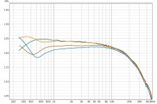
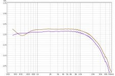
The curves obtained at 2.5" are almost the same as those obtained at 3 feet, so I think the wave is planar enough.
Giving the taser the same treatment with a 3.3ohm resistor across the primary, the resulting curves for the EM258 nearly overlap. So it looks like this could be generalized to various devices, but the taser is the most adaptable source because it can make louder sparks even when damped. Attached the rough curve is the taser, the red curve is the previous result with the Olympian, just with frequency dependent windowing.
It's hard to know when I'm "done" because of lack of experience and the results have been unpredictable in the past. With some of the distortions there has also been the possibility of getting something deceptively close to the calibration curve but actually ridiculous.
Attachments
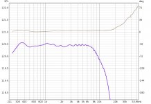
Here is a zoom on that curve. Not sure why the phase is flat at 2.6 degrees, or what it should be. All I know is the results are the most useful when I time align the impulse to the group delay of the upper midrange where it is flat. The group delay steps back by 2mm above 10KHz, I assume because the wavelength approaches the size of the capsule.
Attachments
- Home
- Design & Build
- Equipment & Tools
- Spark calibration of microphones