I tried the EM272 with a different spark gap in a few different orientations. I used the foam spark gap from post #58:
Spark calibration of microphones
So this gives some idea of the variation that can come from the spark gap assembly.
Spark calibration of microphones
So this gives some idea of the variation that can come from the spark gap assembly.
Attachments

I was right, the LF anomaly is still there. I was using the wrong output from my script, so it had an unintentional HP filter at 1KHz, which was, for the millionth time, hiding the LF anomaly. I swear, it just never ends.
It's clearly there because sometimes it switches polarity. Even with the mic 3 feet away, it's still there.
It's clearly there because sometimes it switches polarity. Even with the mic 3 feet away, it's still there.
I know the state of this project must seem pretty abysmal at this point, but I haven't quite given up yet.
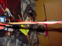
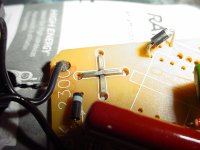
I did get around to trying the most unobstructive spark gap and microphone stand I could think of (attached). I did get a very clean decay in the impulse response, but the LF anomaly is still there. For the microphone capsule a bamboo skewer wedges perfectly between the wires in back to suspend the microphone in a controllable manner. However the skewer tends to wobble and subsonic noise is the enemy of doublets. The amount of rumble coming from the mic when the train passes through town is surprising. It seems there would be an advantage to mounting the microphone so that it is least susceptible to ground bounce.
The spark gap is two bamboo skewers with wire secured by coiling around the tips. This is fiddly but I made it work.
This gave minimal reflections in the first 1ms, but the LF anomaly is still there. What I know about the LF anomaly:
1: It correlates more with spark gap size than anything else. When minimized it does begin to correlate with SPL and distance more.
2: It may change with spark generator even if the gap remains unchanged.
3: It's slope changes. It may be very gradual or it may manifest as a 6db/oct slope. Perhaps appearing gradual is just a consequence of the corner frequency being lower.
4: It appears to manifest as a level shift during the doublet and then gradual return to zero alike a DC filter. This is consistent with asymmetry in the doublet itself or in the capsule electronics.
5: The LF anomaly appears the same through 2 ADCs connected to the same microphone. So the error seems to be narrowed down to the capsule itself, with a slight possibility of being part of the acoustic wave.
6: It is coincident with the acoustic wave and not the spark impulse the mic picks up.
7: The LF anomaly appears to be reduced by shunting the 2-terminal capsule with a 100nF capacitor, but then SNR suffers from ADC noise. It could be this just helps hide it.
8: It sometimes switches polarity between a positive and negative level shift. This would be consistent with nearing positive or negative limits at the time the doublet is recorded. Perhaps related to noise occurring at the same time.
I finally found a battery for the taser, and tested it with a 1mm gap. The results are shown in the attachments compared to the coilpack source. These are taken with the bulky adjustable spark gap, not the spark gap pictured.
Unfortunately I can't go past 1.3ms with the taser source because of some acoustic interference, it may be from the taser's internal spark gap.
Attachments


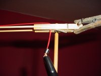
The taser died while trying to tune in the new setup. I made a new spark gap assembly by gluing skewers to another clothespin. The charts looked very smooth without much windowing.
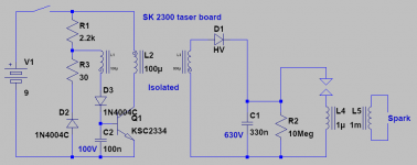
Inside the taser is a flyback circuit charging a 330nF capacitor which discharges into the the primary of the output transformer through a spark gap.
The big problem with the taser source is that the flyback converter is so noisy that the E-field drowns out the doublets in the recording. So I wasn't actually able to get it to work very well.
It appears to be the flyback transformer in the taser that failed, since the transistor tests normal Hfe. I can still charge the 330nF cap by tapping the battery across the flyback transformer, so it looks like it may be the feedback winding that's bad or possibly something I didn't consider.
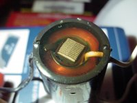
The output transformer is a long piece of laminated steel with windings around it and potted inside a black cup with clear epoxy.
The noise appears to have come from the leakage capacitance of the flyback transformer permitting everything after that point to float at some fraction of the flyback AC signal.
Inside the taser is a flyback circuit charging a 330nF capacitor which discharges into the the primary of the output transformer through a spark gap.
The big problem with the taser source is that the flyback converter is so noisy that the E-field drowns out the doublets in the recording. So I wasn't actually able to get it to work very well.
It appears to be the flyback transformer in the taser that failed, since the transistor tests normal Hfe. I can still charge the 330nF cap by tapping the battery across the flyback transformer, so it looks like it may be the feedback winding that's bad or possibly something I didn't consider.
The output transformer is a long piece of laminated steel with windings around it and potted inside a black cup with clear epoxy.
The noise appears to have come from the leakage capacitance of the flyback transformer permitting everything after that point to float at some fraction of the flyback AC signal.
Attachments
Last edited:
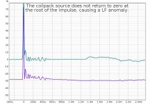
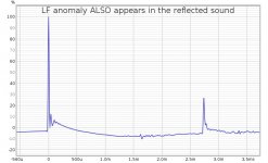
Going back to the coilpack, here is an impulse reponse that shows the LF anomaly is present in the reflected sound and not just the primary wave. So this strongly suggests it is in fact acoustic in origin. This is with about a 4mm gap using the Ford coilpack.
Perhaps this could be glow discharge as the remaining energy in the coil prevents the arc from extinguishing.
If it is that simple, maybe a smaller inductor in parallel with the primary, or a snubber will work.
Perhaps this could be glow discharge as the remaining energy in the coil prevents the arc from extinguishing.
If it is that simple, maybe a smaller inductor in parallel with the primary, or a snubber will work.
Attachments
I still find this an interesting topic. Had to go back to post #1 to see what is the goal with the thread. Could not find anything really. Is it just a happy tech investigation or is there a specific goal with the activity. Honest and sincere question.
//
//
I'm trying to work out how to get a cleanly produced and recorded doublet. The LF anomaly is confusing because I have never seen this documented anywhere, and there are plenty of references in this thread.
I switched back to the coilpack because the taser failed. Different snubbers give interesting results with the coilpack, but the taser seems to work right out of the box except for the massive interference caused by the internal flyback converter.
I switched back to the coilpack because the taser failed. Different snubbers give interesting results with the coilpack, but the taser seems to work right out of the box except for the massive interference caused by the internal flyback converter.
Today I got out the old Olympian GM-12 gas appliance lighter. I avoided using this one because of the interference it causes. It seems to have a fast risetime. For some reason it will spark through the silicone insulation of my alligator clips whereas the taser and coilpack would not. This caused an inconvenience due to the fact that I could no longer twist the wires together to reduce interference. I managed to find a compromise, winding both wires around the spark gap boom and being careful of the distance.
Once the interference is at a tolerable level it actually looks like this sparker is fairly well damped. On the impulse response the E-field has no ringing. However I can't remote trigger because wire of any sort connected to the sparker radiate too much E-field. The ferrite bead application here is crucial.
With this sparker and the new spark gap assembly, I can turn frequency dependent windowing all the way down to 2 cycles with almost no change to the HF response, so this is a very very clean setup.
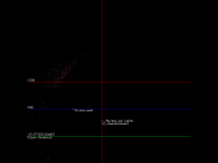
I've attached the impulse response and chart of a measurement with this setup which you can run in REW or your software of choice.
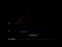
You can also see that I updated my script with a scatter plot to help with setting the slicer settings. The dots go from white to red over time so you can see here there was some drift in the spark output over the 500 sparks in this plot. Everything below the white line is culled and I would have had better results by reducing my preamp by about 6db.
It looks like I may finally be approaching something usable.
Once the interference is at a tolerable level it actually looks like this sparker is fairly well damped. On the impulse response the E-field has no ringing. However I can't remote trigger because wire of any sort connected to the sparker radiate too much E-field. The ferrite bead application here is crucial.
With this sparker and the new spark gap assembly, I can turn frequency dependent windowing all the way down to 2 cycles with almost no change to the HF response, so this is a very very clean setup.
I've attached the impulse response and chart of a measurement with this setup which you can run in REW or your software of choice.
You can also see that I updated my script with a scatter plot to help with setting the slicer settings. The dots go from white to red over time so you can see here there was some drift in the spark output over the 500 sparks in this plot. Everything below the white line is culled and I would have had better results by reducing my preamp by about 6db.
It looks like I may finally be approaching something usable.
Attachments


I'm trying to work out how to get a cleanly produced and recorded doublet. The LF anomaly is confusing because I have never seen this documented anywhere, and there are plenty of references in this thread.
Earthworks mentions this in their article on microphone calibration. This was my first inspiration and why I don't bother with sub 500Hz or so response. You will notice both Geffel and B&K only go down to 3k, the implication of the Geffel plots is that they assume ideal piston response below that (no features at all below 3K).
http://recordinghacks.com/pdf/earthworks/how-earthworks-measures-mics.pdf
Last edited:
Aside from environmental reflections, what do you think sets the LF limit for spark calibration, assuming we can average as many sparks as we want to reduce the noise floor?
At ultrasonic frequencies the EM258 acoustic center moves forward by 1.37mm.
I figured out what was wrong with the taser. The internal charging transformer did not observe clearance limits for 400V output. The output winding was charred from arcing. This must be what was causing so much E-field interference. It was unsalvageable, but I did learn the turn counts. I may try to substitute the taser output coil into the Olympian sparker.
I think the Olympian sparker has more interference due to the iron or ferrite core whereas the taser has a laminated steel core.
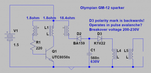
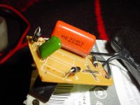
This is what is in the Olympian sparker. It appears the K1V22 diode is used as an avalanche pulser. It's polarity marking is actually backwards so I imagine these were a messed up production run sold at a discount. I've seen only one other batch of diodes with sporadically reversed markings.
Using an avalanche diode does appear to be a relatively quiet way of achieving well controlled lower-energy sparks. The Vishay BYG22a seems like a modern equivalent here. I suppose it won't have the uncertainty that a spark gap does.
Using an avalanche diode does appear to be a relatively quiet way of achieving well controlled lower-energy sparks. The Vishay BYG22a seems like a modern equivalent here. I suppose it won't have the uncertainty that a spark gap does.
Attachments
Last edited:
Aside from environmental reflections, what do you think sets the LF limit for spark calibration, assuming we can average as many sparks as we want to reduce the noise floor?
The leakage of the DC bin (0) into the low frequencies has a large effect, much largerthan you might think. You can remove everything but the 12 samples of the doublet and find that tiny tweeks to one sample near the tails will make large differences below a few 100 Hz. With a little work you can get a nearly perfect response down to 50 Hz or less. Of course the response immediately after the doublet is part of the mics response until there are reflections. In general you have to include the entire region after in the FFT to encompass the longest wavelength you want. The room/gear reflections must all be eliminated.
Last edited:
My script automatically removes DC from the output, so spectral leakage is minimized along with averaging. Although an impulse has a DC component, so technically I may be causing a small amount. I can't easily remove DC before the lowpass filter (and I mean an actual DC shift, not a hipass filter).
I designed a 2-transistor boost converter to step up a C battery to hopefully something high enough to fire the taser. I got to 427V with a CRT trafo core and some wire on the radioshack solder spool I just used up. It is just a single winding.
The voltage seems too low to fire a spark gap, although it will fire the avalanche diode in the sparker.
I can't get any of my diodes to avalanche. I have some actual avalanche diodes but I don't think I can get to 700V with this circuit. Maybe with the scope I can figure out what is limiting the voltage.
The taser's internal spark gap had worn down, so it was requiring over 850V to fire the spark gap using a 630V capacitor... This was probably why the flyback trafo's secondary started arcing. The capacitor is a champ though.
I fixed my converter and got the taser working more or less like originally, but without the massive E-field interference and with some adjustability in the repetition rate.
The results look promising, but there is a step in the impulse response with no physical counterpart as far as I can determine, so I may be looking for interference again.
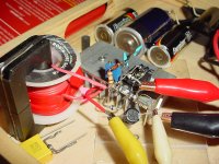
I suspect the lurkers are hungry for pictures, so here you go. Internals of the taser and my P2P converter. I call it the frankentaser.
The scatter plot shows the spark intensity is more variable than with the Olympian sparker which has the best consistency. The coilpack is a bit more consistent than the taser, which I think just shows the variability introduced by adding another spark gap to the system.
I added shims to the CRT flyback core to raise the converter frequency and also reduce the noise. Maybe a lot of the noise was actually from core saturation? I think a CRT flyback generally has fewer primary windings and runs at a higher frequency than what I had so that checks out.
Attachments


Last edited:
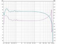
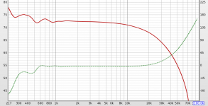
Here is a test of the EM258 with the frankentaser. Everything is very clean, phase shows a 4 degree offset or allpass characteristic, which decreases as I reduce the SPL, so I think I am in the territory of distortion-induced error or imperfect doublets. The allpass behavior seems to show up as the impulse being smeared to the right.
Another sign that it is distortion-induced error is the fact that if I get any louder, the LF anomaly suddenly appears as the impulse under or overshoots the falling root. This corresponds crudely to a peak of about 200mV. So I will note that I should not set my preamp below a certain level if I am recording sparks near 0dbFS.
I'm not sure however why there is 4-5db drop at 20KHz. This seems to be specific to the taser as a spark generator. I can try reducing the capacitor but if the spark had enough energy to limit at 20KHz it should be obvious in the SPL. It doesn't correlate with spark length although I should confirm this with more tests.
If anything the spark spectrum seems to correlate with the HV transformer used. This suggests to me that it is stored energy in the HV coil that may be the main factor at 10-20KHz.
Attachments
Last edited:
Wyber found that too, the problem is that the physics of the compression and rarefaction halves of the wave are totally different and it is not possible to get a sharp edge on the cooling half. There is also the problem that extending the "flat" part of the spectrum reduces SNR. I see they went way below Wyber and I can't read how they dealt with that issue in terms of getting the mic that close to the spark, ambient noise, etc.
This appears as an interesting explanation why the impulse response is smeared toward the right giving an allpass characteristic. And the taser is a more energetic spark than the coilpack or gas lighter.
Let's say the taser charges the 330nF capacitor to 600V when it fires. That is 59mJ. This is about half of the 0.12J shown in Wyber's chart included in the above post.
The Olympian sparker on the other hand is 200V at 560nF which is 11.2mJ.
So maybe reducing the capacitor in the taser is the right idea. I must confess I had the wrong idea how to calculate joules so I didn't think the spark energy was high enough to show these effects...
- Home
- Design & Build
- Equipment & Tools
- Spark calibration of microphones