Here is a paper on the acoustic center of B&K 4160 and 4180 microphone acoustic centers:
https://backend.orbit.dtu.dk/ws/portalfiles/portal/4302125/Barrera-Figueroa.pdf
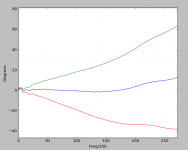
To me it makes sense that a tube microphone like this will have an acoustic center that moves back as frequency decreases. At high frequencies the wave diffracts from the face of the microphone but at low frequencies there is less diffraction and so the mic body reduces the volume of the wave, increasing it's pressure. As frequency decreases diffraction occurs further back the microphone tube.
In the case of a bare mic capsule like what I am using, there is no large mic body to cause this effect so I see very little movement of the acoustic center. That's my thinking anyways.
I think it is a mistake to assume that there is something wrong with my measurements because my microphones don't have a tube body.
https://backend.orbit.dtu.dk/ws/portalfiles/portal/4302125/Barrera-Figueroa.pdf
To me it makes sense that a tube microphone like this will have an acoustic center that moves back as frequency decreases. At high frequencies the wave diffracts from the face of the microphone but at low frequencies there is less diffraction and so the mic body reduces the volume of the wave, increasing it's pressure. As frequency decreases diffraction occurs further back the microphone tube.
In the case of a bare mic capsule like what I am using, there is no large mic body to cause this effect so I see very little movement of the acoustic center. That's my thinking anyways.
I think it is a mistake to assume that there is something wrong with my measurements because my microphones don't have a tube body.
I'm not sure exactly how they are determining the position of the acoustic center. They seem to be assuming that a response variation is due to distance from the source, and extrapolating from the inverse law. This could of course place the acoustic center of any typical microphone meters away from the microphone regardless of the timing of the wave. This acoustic center would also be proportional to the distance from the source. So I think they must be doing something in addition to that to get valid results.
OK OK, I don't see how these effects matter to a DIY'er measuring speakers.
Not really, but when I have a question I like to answer it. 1audio has my script, so hopefully we can get on with it soon.
If you were me, what would you do next?
When I started all this there weren't any cheap mics for room EQ that had calibration curves. Recently I went to the web site of one of them and found out they don't check that you bought one to down load the curve. I made up a bunch of serial numbers and noticed that they vary quite a bit more than I thought.
I would probably not spend a lot of time on this. I have run across these nit picky problems before, where even several experts had no idea what was going on. Are there any ordinary audio applications where this makes a noticeable difference in what one would do?
BTW when I shift the impulse to get flat phase from 1kHz to 20kHz on those plots you sent I get T=0 at exactly the peak of the impulse but the phase has a constant offset. I can make some plots to compare, I only use Matlab type tools.
Last edited:
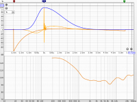
I had a constant phase offset of 2-3 degrees on the latest tests with T=0 at the peak, which is roughly where the 7KHz delay group is. Setting T=0 at the 40KHz delay group removes the offset and gives the flattest phase. Setting T=0 for minimum phase (90 degrees at 30KHz) puts T=0 at the beginning of the impulse about where the doublet would be.
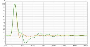
Here is the impulse response of that measurement.
Here is the impulse response of that measurement.
Attachments
I just recorded a quick test and sent it to Keantoken to see if my setup will work. if its a go I'll set up better acoustically and test several mikes to see what can be learned. The interference from the ignition coil is pretty strong and I hope I minimized it, waiting to see.
looking at the current waveform and the trigger pulse there seems to be very little jitter on the current. I'll set up to catch the current and the voltage waveforms and I think I can record 3+ channels simutaneously. Not sure if that would help.
looking at the current waveform and the trigger pulse there seems to be very little jitter on the current. I'll set up to catch the current and the voltage waveforms and I think I can record 3+ channels simutaneously. Not sure if that would help.
I had a constant phase offset of 2-3 degrees on the latest tests with T=0 at the peak, which is roughly where the 7KHz delay group is. Setting T=0 at the 40KHz delay group removes the offset and gives the flattest phase. Setting T=0 for minimum phase (90 degrees at 30KHz) puts T=0 at the beginning of the impulse about where the doublet would be.
I'm not sure what you mean by "set T=0 at the xkHz group" and you can't change the phase offset (you can only rotate it) by simply time shifting a signal. In any case here is what I got on the last thing you posted. This is peak at T=0 and +- 1 sample period. The phase change per sample shift is 45 degrees at 24kHz as it should be. From this a small sub-sample delay would make the phase almost perfectly flat out to 15kHz or so with a small shift beyond that as expected. I don't trust relying on what is going on at high frequencies for much of anything.
Attachments
I'll set up to catch the current and the voltage waveforms and I think I can record 3+ channels simutaneously. Not sure if that would help.
Generally the preamp noise is below the acoustic noise floor, unless you are recording quiet sparks from a distance due to interference, in which case parallel channels can reduce the noise just enough if you only need a little less noise.
I can't do anything with the I/V waveforms using my current setup, although they would be interesting to see.
Linux should support standard USB sound input.
I got the email unstuck. Let's see if it's going in then right direction and then I'll set up for more extensive testing.
I need to do a new Linux install. Ubuntu is based on Debian. That should work with your script I think. Any cautions?
I need to do a new Linux install. Ubuntu is based on Debian. That should work with your script I think. Any cautions?
If your version of sox is out of date, there should be a Launchpad ppa or something you can install it from. I don't think that will be an issue but it may. Getting things to work between Ubuntu and Debian can be a real pain, sometimes there are subtle issues like some utility uses a different regex syntax.
Your recording has a level of interference I've never seen. I don't see any acoustic overload which is good, but the interference leaves a DC drift which really limits the usable frequency range. Have you tried shorting the spark terminals and then seeing what the interference looks like?
Your recording has a level of interference I've never seen. I don't see any acoustic overload which is good, but the interference leaves a DC drift which really limits the usable frequency range. Have you tried shorting the spark terminals and then seeing what the interference looks like?
Attachments
Last edited:
Try limit the spark to 1mm or less with pointed electrodes and put a 220k resistor across the spark gap. This can reduce interference quite a lot and possibly damp the coil. I was able to use a 1/2W carbon film resistor this way with the Olympian.
The gating effect on the audio seems like a driver bug though. Does it only happen while the sparker is running?
The main thing is to isolate the voltage transients to as small an area as possible and what cannot be shrunk should be balanced like a dipole so there is an area of cancellation for the microphone.
I think there is some big e-wave coming from the coil. The wires are all tightly twisted and well away but I'll explore the radiated noise. The gap is around 1 MM or less. it will easily jump 1/2" but that's really loud and really big emi. This stuff is always hard to instrument. Same problems with surge testing, making sure you are seeing what you think you are. The low frequency stuff really has me puzzled as well.
Lots to explore tomorrow.
Lots to explore tomorrow.
I have made progress. I changed the cap driving the coil from 2 uF to .18 uF. Less output voltage but a shorter spark and lots less interference with everything. I also ditched Audacity, it was suddenly wonky and switched to Reaper and ASIO. I should have some much better recordings later today. How many pulses are enough? Its easy to record lots with this setup. And the rep rate can be set from 1/second to 60/second.
I usually go for 20 to 40 for functional tests, but 128 or more when I start paying attention to the acoustics. Repetition rate depends on the decay of the room, but I would go with below 10 per second.
The waveform at the spark event looks like multiple discharges, when my setup is working well I just get one single blip. For that microphone the impulse response should be much cleaner.
Is your device a CDI type circuit? Does it charge the capacitor to a high voltage or is it just 12V like a car ignition? The capacitor likely needs to be damped. A parallel resistor and/or diode can help, or a resistor across the HV leads may also work.
FYI the resonance of my sparkers is 40-50KHz, yours is at 30. So maybe you could still reduce the capacitor.
Last edited:
One scope down, to be sent out for repair. lost one channel. Off to a good start.
Pulled out the Tek 720P the P6015 and a Pearson current transformer.
Still getting problems from EMI into the scope. It has been long an issue with the THS stuff and it seems any other scope I try.
Voltage peak during the arc is 10 Kv, 20 KV open circuit with no damping series resistor. Duration approx 70 uS
I added a 100K resistor in series. It still works! You can see the voltage drop to zero when the arc breaks over, its very fast, a few nS (emi forever!!).
I did try a .01 uF cap and got no spark. .03 uF seems to work.
I'm getting what seems to be vary short arcs, but three acs 60 uS apart. It may be resonances in the coil. If I reduce the series resistance below 100K the EMI screws up the scope. I put a 1 meg resistor in series and it simply arcs over it. 100 K seems OK. However 5 of the 2W 100K in series seems to work fine. Its either 1 arc or two 150 uS apart. I'm not sure yet how to tell which since the voltage switches polarity and still seems to have the fast drop like an arc. When its not arcing the wave is quite smooth, and no emi spikes. Opening the gap seems to eliminate the extra arc but the scope really cannot handle the emi from the arc.
I think the opamp in the mike preamp has a serious EMI problem, which is causing the LF offset issue.
Once I'm reasonably OK with this I'll work on the preamp and then attempt a recording again.
Let's have a moment of silence for Channel A. Let his sacrifice not be in vain.
I'm struggling to understand why your spark generator needs a discharge capacitor for an automotive coilpack, without being able to see a step up converter on the board. I don't see why not use a flyback driver for the coil. I wonder what the primary resistance is?
Try a resistor in parallel with the primary or secondary. Hundreds of Kohm for the secondary or 1-20 ohm for the primary seems like a good start. That is what worked for me. I used 10 ohms for the Olympian (or 220k at the secondary) and 3.3ohms for the taser, carbon comp.
For your coil, 10KHz with 0.18uF means a primary inductance of 1.41mH, and a critical damping resistance of 88 ohms. This is much larger but perhaps believable since your coil is so much larger.
My resonance is 30-40KHz, but seems fast enough to keep the spark alive rather than multiple discharges. When I switched to twin lead I got multiple discharges again, so it seems the lead capacitance plays a role as well.
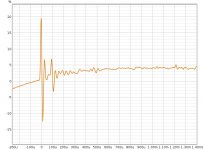
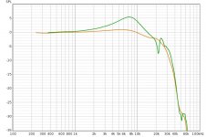
Attached is a comparison of an EM172 in a 22mm tube with a foam plug at the back, with the EM272 without the tube. I'm not sure whether the peak is part of the EM172's response or if it is a result of adding the tube or soldering, but I'm tending toward it just being the capsule's natural response.
I'm struggling to understand why your spark generator needs a discharge capacitor for an automotive coilpack, without being able to see a step up converter on the board. I don't see why not use a flyback driver for the coil. I wonder what the primary resistance is?
Try a resistor in parallel with the primary or secondary. Hundreds of Kohm for the secondary or 1-20 ohm for the primary seems like a good start. That is what worked for me. I used 10 ohms for the Olympian (or 220k at the secondary) and 3.3ohms for the taser, carbon comp.
For your coil, 10KHz with 0.18uF means a primary inductance of 1.41mH, and a critical damping resistance of 88 ohms. This is much larger but perhaps believable since your coil is so much larger.
My resonance is 30-40KHz, but seems fast enough to keep the spark alive rather than multiple discharges. When I switched to twin lead I got multiple discharges again, so it seems the lead capacitance plays a role as well.
Attached is a comparison of an EM172 in a 22mm tube with a foam plug at the back, with the EM272 without the tube. I'm not sure whether the peak is part of the EM172's response or if it is a result of adding the tube or soldering, but I'm tending toward it just being the capsule's natural response.
Attachments
- Home
- Design & Build
- Equipment & Tools
- Spark calibration of microphones