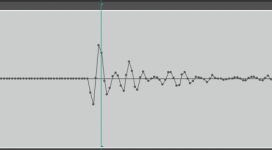
This is a clip from Reaper using its internal EQ set as a low pass filter starting at 100 Hz. It looks almost the same if I start at 2 KHz.
I'm not sure this is helping. Please advise.
Spectrum tells more, the literature I found was talking about the problems going to 0 Hz.. BTW I got my Scarlett 2i2 to work with Audacity/WASAPI.

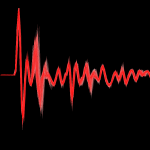
Whatever you did has made the sparks much less consistent. The peak variation is now about 6db. This could be because of a longer spark and/or electrode sharpness and/or slower risetime on the electrode voltage.
Damping the coil may be important for better consistency.
Damping the coil may be important for better consistency.
Attachments

I think something has degraded. It sounds less consistent. I have some other projects I need to attend to and then I'll attempt a cleanup on both the spark gap and the coil. Damping this guy will be interesting. I'm not sure an parallel RC would do the job. I could put a series resistor between the coil and the cap. That may de-Q it enough without inhibiting the spark.
I wanted to try a series resistor but haven't yet. The negative voltage coefficient of carbon comp may be helpful in this case.
For parallel damping you just need a resistor, no need for a capacitor, it does nothing.
For parallel damping you just need a resistor, no need for a capacitor, it does nothing.
I'm looking for a model of the circuit so I can better predict things. I'll instrument the coil next the 400+ voltage on the cap makes that more challenging. The p6015 probe is huge and clumsy to use but the only way to look at these high voltages. I'll stick a current probe in there as well.
Carbon comp resistors are almost the only option for these high transient power applications. Nothing else an handle the peak current without a lot if inductance.
Carbon comp resistors are almost the only option for these high transient power applications. Nothing else an handle the peak current without a lot if inductance.
I'm working on the generator some more. With the components in it now the coil primary peak voltage is 600 and the peak current is 40A. The resonant frequency seems to be around 80 uS. The coil primary is around 2 ohms. I think I know enough about the circuit to sketch it out. Later today. Essentially a triac shorts the series coil cap to trigger the discharge and then it charges through a 50 Ohm resistor. A series resistor between the coil and the cap may be just right to damp the rining. However what value? it may be cut and fit. peak power is 40 X 600 or 24 KW but that's misleading. Figure the time (50 uS) in and its 1.2W per spark or actually less. The scope calculates 18 KW peak. I have some 50 Ohm carbon comps I'll try.
That would be 84 ohms based on the inductance needed to ring at that frequency. In series, 50 ohms would be underdamped, in parallel 50 ohms would be overdamped.
OK, 20 Ohms works pretty well. Lots less ring but still enough to arc 1/8" reliably. Time to work on the spark gap.
I know the mike is good to 120 KHz and have used it with the Pioneer ribbon to 70 KHz. I wonder if the limit is due to the duration of the arc? Or maybe the physical size of the arc?
I'll check the analog link etc. to make sure there is nothing futzing in the background. It seems good to at least 90 KHz per the meter in Reaper. I have no way to go into the mike preamp directly, unlike the 1/2" and 1" mikes. However it has worked in the past.
I'll check the analog link etc. to make sure there is nothing futzing in the background. It seems good to at least 90 KHz per the meter in Reaper. I have no way to go into the mike preamp directly, unlike the 1/2" and 1" mikes. However it has worked in the past.
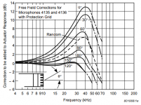
I have measured 70 KHz with the grid on. The accuracy is degraded but its not a low pass filter to that extent. When everything else is stable I'll try it. Thats risky so I'm not going to before I have a good mike stand solution.
That may be the switching supply in the B&K power supply. I'll check on that. I switched from the other ac powered supply to address the hum. I think I know where the hum is coming from now.
Here is something interesting. Unfortunately it is rather vague. I don't know if this would also apply to coil-based spark generators.
https://ntrs.nasa.gov/api/citations/19770017962/downloads/19770017962.pdf
Electrical Spark Discharge for Acoustic
Wave Calibration
Two spark calibration probes were built and tested for
this project. The first had 12-inch leads from the capacitor
to the electrodes and the electrodes were mounted 180 from
one another. This design produced considerable electromagnetic interference in the area of the experiment and appeared
to have multiple discharges during each event. A discussion
with engineers working on spark-discharge experiments in the
Vanderbilt Chemical Engineering Department revealed that
there can be a problem with fields interacting with the discharge when the electrodes are mounted at 90 and at 180.
Thus, to avoid reverberations during the discharge, the
Page 84
electrodes should be mounted at an angle between 89 and 85.
The second spark-probe design was constructed with much
shorter leads from the capacitors to the electrodes, and the
angle between the tungsten electrodes was approximately 88.
The capacitance was 0.025 uF, and the power supply was
current-limiting to provide 10 uA at 3500 volts.
https://ntrs.nasa.gov/api/citations/19770017962/downloads/19770017962.pdf
I know the mike is good to 120 KHz and have used it with the Pioneer ribbon to 70 KHz. I wonder if the limit is due to the duration of the arc? Or maybe the physical size of the arc?
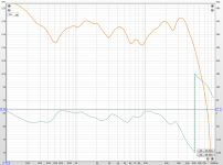
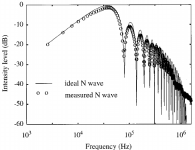
Keantoken's file show the HF null inherent in the N-wave spectra which is a Bessel function.
On the Frequency Spectrum of N Waves
The Journal of the Acoustical Society of America 41, 528 (1967)
Attachments
Last edited:
I would think so, but I have never seen an obvious agreement between my measurements and the papers. Any nulls always seem to be near or above 96KHz. Most of the time the nulls seem to be related to spark trains and disappear when those are eliminated. I have always wondered if those results are only valid for direct discharge from a capacitor, and not for sparks produced from HV coils.
Last edited:
- Home
- Design & Build
- Equipment & Tools
- Spark calibration of microphones