If you leave it powered off for a while (how long?), will it repeat this?
Does the voltage gradually build or does it snap from 0v to 32 v instantly?
Does the voltage gradually build or does it snap from 0v to 32 v instantly?
The voltage increase was immediate. I was alternating the leads of the DMM between the left and the right channels and after about 3-5x going back and forth it then showed the 32Vdc. On the previous check seconds before it was -8mvdc.
If I am to leave it running Im guessing I should put the circuit board back on the heatsink. Also the last time I let it run over 30secs it began smelling like burning plastic and I had to shut it down. The transistors on the driver board start heating up and giving off that smell.
If I am to leave it running Im guessing I should put the circuit board back on the heatsink. Also the last time I let it run over 30secs it began smelling like burning plastic and I had to shut it down. The transistors on the driver board start heating up and giving off that smell.
While it's at near 0v, will it produce audio?
You can just power up for a few seconds to check for audio. You don't want to drive speakers/loads without heatsinking and don't want to risk driving DC to the load.
Do you have your scope working?
You can just power up for a few seconds to check for audio. You don't want to drive speakers/loads without heatsinking and don't want to risk driving DC to the load.
Do you have your scope working?
Now that Q2-Q6 have the base and collector shorted it immediately goes to 32Vdc. I tried turning it on/off over 10x hoping it would stop being shorted and therefore not have the 32Vdc but it didn’t happen. If the same pattern as before holds true then reinstalling and then removing Q2 should stop the short temporarily to perform your audio test. My fear is blowing another speaker. As you may recall the bipolar capacitor is not filtering out the 32vdc so it wont protect my speakers.
I haven’t bought an oscilloscope. Do I need one now?
I haven’t bought an oscilloscope. Do I need one now?
See if the voltage will go away if you leave it off longer.
There may be something wrong with the cap if it passes DC. Are you sure it's bipolar?
How much DC was passing through the cap?
There may be something wrong with the cap if it passes DC. Are you sure it's bipolar?
How much DC was passing through the cap?
I left it off overnight and the pins are still shorted and the right channel still has 32vdc. As for the bipolar caps I tried two and they both let all the 32vdc through.
Something interesting happened. I reinserted Q2 turned it on and off and removed it and turned it on. The 32vdc didnt appear at all but after 30 secs still had to shut it down because of the overheating transistor on the driver board. After shutting it down the base and collector pins were shorted.
If the caps are large, they will take time to charge and will appear to pass DC for that time.
A 120v incandescent lamp may make a better test load. You'd have to watch current and heating of transistors since the lamp may pass more current than expected if the filament doesn't heat sufficiently. A low wattage would be better than a high wattage.
Is there any heatsink compound that could be hiding a strand of wire that could be causing the intermittent short?
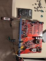
Yes the caps are large. 100uf 100v caps. If dc passes through them even for a few seconds they will fry my speakers. I tried again with the bipolar cap and gave it 20secs until the driver transistor got to 180F. Still was putting out 32vdc through the cap. Im attaching a pic of my test setup in action.
So are you suggesting that I hook up an old school light bulb to the right channel speaker?
I cleaned off all the heatsink compound again. Used canned air to blow off anything on both sides of the pcb and checked it under a magnifying glass. Everything looks clean.
So are you suggesting that I hook up an old school light bulb to the right channel speaker?
I cleaned off all the heatsink compound again. Used canned air to blow off anything on both sides of the pcb and checked it under a magnifying glass. Everything looks clean.
Attachments
Last edited:
Use the lamp in place of the speaker and cap.
Do all outputs on the right channel heat up evenly?
Do all outputs on the right channel heat up evenly?
The output transistors dont heat up. Its the one transistor on the driver board that the thermometer is touching in my pic. This didn’t change after swapping the driver boards so it’s not the transistor nor the board.
Last edited:
Thank you Perry. If this helps, I traced the transistor on the Driver Board to find what it's connected to in the schematic for the amp. The transistor is a C3789. Here is the datasheet:
https://datasheetspdf.com/pdf/769778/SanyoSemiconDevice/C3789/1
The Emitter is connected through a 49ohm resistor to the driver Board Pin #1 (Vee). This pin is then connected to the amp's -rail voltage.
The Collector is connected directly to Driver Board Pin #2(Drive-). Which is then connected to the base leg of all Q10-Q14 transistors (the complementary transistors to the shorted group Q2-Q6).
The Base is connected directly to Driver Board Pin #3(Base-). Goes nowhere according to the schematic.
Thanks again for being so helpful and patient!
Last edited:
Why were you having trouble removing the output transistors?
Didn't you say that you have a new soldering iron?
What make/model?
Didn't you say that you have a new soldering iron?
What make/model?
I have a beautiful new soldering station! Its a YIHUA 939D+. I think it’s a technique problem not a soldering station issue. I removed the driver boards with ease. The output transistors never just falls off within seconds like you said it should. I feel I have to pull which is how I broke the leg off the one above. Ive tried wicking each hole. But it never wicks it all and disconnects the pin from the hole. Ive tried suction pumping each hole. But also never loosens the pin from the hole. Ive tried spreading solder over all three holes to heat them simultaneously. But the solder just gets sucked up to the other side of the board or up the transistors pins. In all three methods I have to apply heat for long periods of time just to make a little progress on each leg.
What temperature are you using?
Bridging all 3 legs with the transistor standing perpendicular to the board, the transistor should fall out or do so with very little force.
Don't put your hand under the molten solder. If you have bamboo skewers, stick one through the hole and push down from the side while heating.
Bridging all 3 legs with the transistor standing perpendicular to the board, the transistor should fall out or do so with very little force.
Don't put your hand under the molten solder. If you have bamboo skewers, stick one through the hole and push down from the side while heating.
Last edited:
I have it set to 700F. So your recommended technique is apply solder to bridge and then push down the pins as you heat each one?
You heat all 3 at one time with the transistor perfectly perpendicular to the board (hanging below the board). You shouldn't need to push and pushing on the legs (unless they're cut really short) won't conduct much heat to the solder.
If you have a pair of hemostats, their weight (clipped onto the hanging transistor) will generally be enough.
If you have a pair of hemostats, their weight (clipped onto the hanging transistor) will generally be enough.
- Home
- General Interest
- Car Audio
- Soundstream Rubicon 502 with DC voltage in right channel