
Yeah, I hate you all very, very much...
😀
Listening to i currently and I must say, I very fond of what I hear.
Maybe I will throw in a couple of pics of my test chassis later, right now I don't want to disconnect it. 😉
Best regards,
Mags
😀
Listening to i currently and I must say, I very fond of what I hear.
Maybe I will throw in a couple of pics of my test chassis later, right now I don't want to disconnect it. 😉
Best regards,
Mags
Lifted Pad..help!
Hi All, this my first post and unforntunatley its not a happy one....
Just finishing the mods described to my rev d board and I managed to lift right handside pad for c3 when removing it and now is no way of bridging it(the almost the last thing I had to do too!!). Can anybody tell me where to try and jumper to, I've tried to work it out but I'm really very new at all this and am feeling pretty stupid at the moment..any help much appreciated!
Re: Lifted Pad..help!
Hi 🙂
Well this is one of those things we have all done at some time or another, all you need to do solder a very thin guage wire (wire wrap wire) to the trace leading to/away from the pad, just gently scrape the varnish off before until you see copper.
Very fiddly but if you take your time you should be able to do it.
Then snip the wire to the required length and solder to the other pad....
Good luck
Jazute said:Hi All, this my first post and unforntunatley its not a happy one....
Just finishing the mods described to my rev d board and I managed to lift right handside pad for c3 when removing it and now is no way of bridging it(the almost the last thing I had to do too!!). Can anybody tell me where to try and jumper to, I've tried to work it out but I'm really very new at all this and am feeling pretty stupid at the moment..any help much appreciated!
Hi 🙂
Well this is one of those things we have all done at some time or another, all you need to do solder a very thin guage wire (wire wrap wire) to the trace leading to/away from the pad, just gently scrape the varnish off before until you see copper.
Very fiddly but if you take your time you should be able to do it.
Then snip the wire to the required length and solder to the other pad....
Good luck
Noob Q - What parts are really needed?
I am struggling on how to identify what parts are necessary for the mods (specifically caps, pot). I went to parts express and found this for the input caps.
http://www.partsexpress.com/pe/pshowdetl.cfm?&Partnumber=027-858&scqty=4
They have auricaps but not 200V only 400V (is that okay?).
And maybe this to replace the C10 cap:
http://www.partsexpress.com/pe/pshowdetl.cfm?&Partnumber=020-1046&scqty=10
or this?
http://www.partsexpress.com/pe/pshowdetl.cfm?&Partnumber=020-1050&scqty=2
but I'm not sure how to tell if they are low esr, or even acceptable as a replacement for the stock cap.
I went to mouser to check out the caps there but my search for just Nichicon turned up 3 pages of 680uF caps. Okay, 5-6 after limiting to radial and 16V, but again, which one?
I also noticed shielded requirements from the pot but any recs on what to get for shielded wire (and does parts express carry it)? Cat5E or Cat 6 I see being discussed.
Obviously an argument can be made I shouldn't be trying this if I don't understand it, but I'd still like to try.
Obviously an argument can be made I shouldn't be trying this if I don't understand it, but I'd still like to try.
No argument there, we all have to start somewhere😀
Digikey have a beter offering than P/Express, the panasonic FM's are very good.
Shielded wire? There are so many but get one that is small/flexible enough so that you don't start breaking joints when you start moving it about, like this stuff:
UK supplier
....it's 2.8mm diameter by the way, ignore the typo on the page! I'm sure digikey will have a similar offering... probably even better quality.
Good luck with the mods
Thanx - I found the 1200 Panny FM caps, but no idea how to locate the input caps and if I did, which ones are okay, unless someone says otherwise, I'll go with these...
http://www.partsexpress.com/pe/psho...027-858&scqty=4
unless it's okay to use the 400V auricaps that partsexpress has instead of the 200V. I'm guessing it is but don't want to put something in that shouldn't be there.
http://www.partsexpress.com/pe/psho...027-858&scqty=4
unless it's okay to use the 400V auricaps that partsexpress has instead of the 200V. I'm guessing it is but don't want to put something in that shouldn't be there.
FTJoe said:Thanx - I found the 1200 Panny FM caps, but no idea how to locate the input caps and if I did, which ones are okay, unless someone says otherwise, I'll go with these...
http://www.partsexpress.com/pe/psho...027-858&scqty=4
unless it's okay to use the 400V auricaps that partsexpress has instead of the 200V. I'm guessing it is but don't want to put something in that shouldn't be there.
Make sure the replacement cap is 8mm diameter.... 10mm at a tight squeeze!
For input caps voltage is not realy an issue but sonics are... have a look at the various capacitor threads on this forum to decide.
I use Obliggato's but they are BIG!
While I'm waiting for parts, maybe I can ask another question. I plan on putting a pot on, but ultimately I'm going to run the T-Amp with a Squeezebox so I really don't need volume control. If I were to remove the pot what so I need to do to make sure everything is okay? Do I just makea complete circuit with the ground and the inputs. I thought I saw somewhere else I should do something else with the ground as well.
Also, any issue in having the T-Amp running full out, distortion, etc?
Also, any issue in having the T-Amp running full out, distortion, etc?
FTJoe. You have to add resistors if you want to use it as a power amp. I seem to remember there was thread called something like "T-Amp as power amp". I posted a diagram of where the resistors were to be connected and what values I had used.
Thanx Puffin - makes sense I guess (it's been 30 years since my high school electronics course).
I was running a stealth modded(tm)🙂 SI T-Amp as power amp for quite some time.
I didn't use any resistors, just removed the pot and connected it to my line-level preamp(with no pot). I was using 2 soundcards as sources at the time and it was working great. No problem with distortion or hiss.
Later, I got a USB DAC and connected it to the same preamp and the little T-Amp started spitting noise and hissing like crazy. I lowered the volume digitally (loosing bits), but the amp was still very very noisy.
I soldered the old pot back and it was ok again.
If Squeezebox has a volume control on DAC (like soundcards), you should be fine.
I didn't use any resistors, just removed the pot and connected it to my line-level preamp(with no pot). I was using 2 soundcards as sources at the time and it was working great. No problem with distortion or hiss.
Later, I got a USB DAC and connected it to the same preamp and the little T-Amp started spitting noise and hissing like crazy. I lowered the volume digitally (loosing bits), but the amp was still very very noisy.
I soldered the old pot back
and it was ok again.If Squeezebox has a volume control on DAC (like soundcards), you should be fine.
Thanx but it might be a moot point. Not sure where I should go now, I performed the minimum surgery and now only the right channel works. Did I screw up the bridge. Removed the two resistors and removed and jumped the two capacitors. I'm sure the problem's on the board as it doesn't matter which input is connected, only the right (middle of the three wires) works. Bummer...searching now for answers...
Didn't see how to edit my last post. Definitely a problem with the bridge, C3 was an issue. I splashed the solder around and voila, music. Sounds okay, running through an old pair of Orb speakers, disconnected the speakers and letting it just run for a while to "break in". Next I'll do the connections for real, using shielded mic wire for the inputs, add speaker posts, re-box it and should be good to go...
Bad voltage?
Just put together my first T-amp project - I'm using a 13.8V, 3A regulated power supply. Removed R01, R02, bridged C3, C4, added Solen caps, Noble pot, mini power switch, RCAs. Now I'm measuring 6.8V from speaker binding posts to ground. I don't think this is right - is it? Offset between the pos and neg posts is .08V. Any ideas?
Cheers,
Malcolm
Re: Bad voltage?
6.8V is nearly 1/2 of your 13.8 volt rail. Sounds about right to me.
FYI, the outputs sit at about 1/2 the supply voltage above ground. That's why you can't tie them to ground.
g-horn said:Now I'm measuring 6.8V from speaker binding posts to ground.
6.8V is nearly 1/2 of your 13.8 volt rail. Sounds about right to me.
FYI, the outputs sit at about 1/2 the supply voltage above ground. That's why you can't tie them to ground.
Another dopey question or two. First one I did sounds good, used shielded mic cable for inputs but there is still a hum from the speakers when it's plugged in. The hum goes away when I connect the RCAs to the squeezebox (even with the squeezebox off) so I think I'm okay but is there something I need to do better the next go around?
The mic wire is too big to use in a small box, what are other folks using for input wire? What gauge, is it shielded, or just a twist in the wire, etc.?
The mic wire is too big to use in a small box, what are other folks using for input wire? What gauge, is it shielded, or just a twist in the wire, etc.?
Re: mistake?
Oh dear, you've taken the pads and traces as well.....
Still salvageable though, you just need some wire-wrap wire to bridge from the connector pin (or somewhere up stream of the cap you removed) to the input resistor.
just about to bath the kids so maybe someone else can do the pictures.......
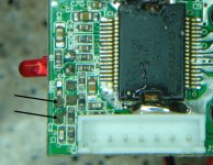
gychang said:I have rev D, just took off C3, C4, did I take off too much?, no place to solder the new caps to (actually wire).
Can this be salvaged?
gychang
Oh dear, you've taken the pads and traces as well.....
Still salvageable though, you just need some wire-wrap wire to bridge from the connector pin (or somewhere up stream of the cap you removed) to the input resistor.
just about to bath the kids so maybe someone else can do the pictures.......
- Status
- Not open for further replies.
- Home
- Amplifiers
- Class D
- Sonic Impact 5066 Parts List & Modifications