Re: Re: mistake?
oops... I would appreciate picture instructions if possible from someone for a newbie like me...
I am not even sure what wire-wrap wire is.
gychang
Lostcause said:
Oh dear, you've taken the pads and traces as well.....
Still salvageable though, you just need some wire-wrap wire to bridge from the connector pin (or somewhere up stream of the cap you removed) to the input resistor.
just about to bath the kids so maybe someone else can do the pictures.......
oops... I would appreciate picture instructions if possible from someone for a newbie like me...
I am not even sure what wire-wrap wire is.
gychang
something like this, thin solid wire with thin, high temperature insulation
http://www.jaycar.com.au/productVie...&pageNumber=&priceMin=&priceMax=&SUBCATID=616
for surface mount work you really, really need a temperature controlled iron. Get a Weller one with a selection of number 7 magnastat tips in various sizes.
next time make a small, snug collar from very fine wire around the capacitor, the wire carries the heat of the iron around to the pad on the other side so they both melt at the same time. You should remove the whole cap gently with both pads melted. it will fall off with a gentle prod from some tweezers.
That looks like too much heat from an uncontrolled soldering iron and levering the capacitor off the board without having both pads melted. Solder is stronger than the glue that holds the copper to the board. Too much heat from a bad iron will severely weaken the glue or even burn it away completely on very cheap circuit boards.
Ironically only experienced solderers can get away with using a cheap soldering iron on delicate jobs.
OzMikeH said:something like this, thin solid wire with thin, high temperature insulation
http://www.jaycar.com.au/productVie...&pageNumber=&priceMin=&priceMax=&SUBCATID=616
for surface mount work you really, really need a temperature controlled iron. Get a Weller one with a selection of number 7 magnastat tips in various sizes.
next time make a small, snug collar from very fine wire around the capacitor, the wire carries the heat of the iron around to the pad on the other side so they both melt at the same time. You should remove the whole cap gently with both pads melted. it will fall off with a gentle prod from some tweezers.
Thanks OzMikeH. collar made from a wire makes sense to melt both sides of the cap so can be lifted off.
Will have to try to look at the schematic and see if the project can be saved...
gychang
now that the pads are gone you need to get the magnifier out and look at which components the fine copper tracks were leading to.
Get your wire-wrap wire, strip about 1mm, solder a piece to each of these components.
then bend the wire to follow where the track went. tack it down on the corners with a dot of supa glue.
stick the new component down upside down where the old component was with a very tiny dot of supa glue, dress the wire wrap wire off so it touches the solder pads on the upside down part, solder it to the part.
Use good quality solder, I prefer Multicore brand. never use the lead free crap. it isn't even useful for making sinkers for fishing.
normal hardware store solder is crap as well.
be aware the fumes from touching supa glue with your iron are very very nasty. never wear contact lenses when soldering a board that has bits of supa glue on it. the fumes sting your eyes like you wouldn't believe, then with contacts it's far worse.
Using a good iron and good solder will make the job ten times easier!
Sorry for hijacking the thread, Greg: there is a lot of soldering advice in Electronics and Parts.
Re: mistake?
It looks as if you may have removed R80 as well 😱 You will have to tread carefully now and make sure you don't lift anything else. Still salvageable at the moment.
gychang said:I have rev D, just took off C3, C4, did I take off too much?, no place to solder the new caps to (actually wire).
Can this be salvaged?
gychang
It looks as if you may have removed R80 as well 😱 You will have to tread carefully now and make sure you don't lift anything else.
Still salvageable at the moment.Re: Re: mistake?
I have found the R80 and replaced it. Not sure how to connect or trace the C3, C4 though... there is no solder trace on the back of the PCB on the latest version of T-amp.
gychang
audio1st said:
It looks as if you may have removed R80 as well 😱 You will have to tread carefully now and make sure you don't lift anything else.
I have found the R80 and replaced it. Not sure how to connect or trace the C3, C4 though... there is no solder trace on the back of the PCB on the latest version of T-amp.
gychang

audio1st said:Hope this picture makes sense, be careful and good luck..
audio1st, thanks very much.
1. I will replace R80.
2. removing R02, R3, what effect will it have? My main purpose was to improve bass by replacing C3,4. (I am not too good at desoldering...)
3. I can do the links as you suggest.
How can I connect my new C3,4?
Your suggestions are very helpful, and I will resurrect this if possible.
gychang
Attachments
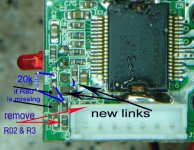
gychang, you are best using the stealth modification when replacing the caps, this is why Audio1st mentions the removal of R02/3.
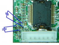
If you are only replacing the caps and placing them in exactly the same position in the circuit then you just need to use the new connection points shown in Audio1st's picture.
Rough and ready picture........
If you are only replacing the caps and placing them in exactly the same position in the circuit then you just need to use the new connection points shown in Audio1st's picture.
Rough and ready picture........
Attachments

Lostcause said:gychang, you are best using the stealth modification when replacing the caps, this is why Audio1st mentions the removal of R02/3.
If you are only replacing the caps and placing them in exactly the same position in the circuit then you just need to use the new connection points shown in Audio1st's picture.
Rough and ready picture........
Lostcause:
thanks very much. If I follow your suggestion. I will end up.
replacing input caps (I have the proper part), without further surgery.?At this point, I want simple solution. I think I soldered the R80 correctly. (I unsoldered it by mistake)
gychang
Attachments
gychang said:
Lostcause:
thanks very much. If I follow your suggestion. I will end up.
replacing input caps (I have the proper part), without further surgery.?At this point, I want simple solution. I think I soldered the R80 correctly. (I unsoldered it by mistake)
gychang
If you just want to replace the caps then yes, use wire-wrap wire or something similarily thin and flexible to connect your new caps to the board as shown.
Don't try and use too thick a wire or you will end up pulling off more components and traces......
Good luck....
Lostcause said:
If you just want to replace the caps then yes, use wire-wrap wire or something similarily thin and flexible to connect your new caps to the board as shown.
Don't try and use too thick a wire or you will end up pulling off more components and traces......
Good luck....
thanks so much. will tackle this soon. I have some thin wires.
gychang
Stock SI T-amp PCB size?
Can anyone tell me the measurements of the stock SI T-amp PCB? It will help in the deciding on an enclosure.
Can anyone tell me the measurements of the stock SI T-amp PCB? It will help in the deciding on an enclosure.
Re: Stock SI T-amp PCB size?
About 3" x 1.5" x 1" minimum in height, allow a little more on the height if you are going to replace caps etc......
nbrophy said:Can anyone tell me the measurements of the stock SI T-amp PCB? It will help in the deciding on an enclosure.
About 3" x 1.5" x 1" minimum in height, allow a little more on the height if you are going to replace caps etc......
What size heaksink for the TA2024 chip
What are the dimensions of the TA2024 chip? Would either of heatsinks below work?
0.75" x 0.53" x 0.50" high
http://www.allelectronics.com/cgi-bin/item/HS-140/search/TO-220_ALUMINUM_HEATSINK_.html
0.75" x 0.6"
http://www.allelectronics.com/cgi-bin/item/HS-132/search/HEATSINK_FOR_DIP_DEVICE,_THM-6010_.html
Re: What size heaksink for the TA2024 chip
Best is to look for RAMDAC heatsinks from eBay seller WLUK. That's where I buy mine.
Also New Egg has some very nice copper ones. Both types come with thermal tape (frag tape).
nbrophy said:Would either of heatsinks below work?
Best is to look for RAMDAC heatsinks from eBay seller WLUK. That's where I buy mine.
Also New Egg has some very nice copper ones. Both types come with thermal tape (frag tape).
TA2024 chip size
Thanks for the suggestion.
According the TA2024 PDF from the Tripath site, the chip dimensions are about 16mm x 11mm (0.630" x 0.437").
Thanks for the suggestion.
According the TA2024 PDF from the Tripath site, the chip dimensions are about 16mm x 11mm (0.630" x 0.437").
Input wiring question
I am looking into reboxing my t-amp. I have what potentially is a dumb question.
I see from panomaniac's photo schematics that when upgrading to a better pot the onboard 3.5mm mini input jack is bypassed in favor of wiring left-in and right-in RCA phono input jacks directly to the pot. I was wonder could the onboard 3.5mm mini input jack also be wired (the PCB left-in and right-in to the pot as in the original T-amp wiring) in conjunction to RCA phono input jacks? I was just curious whether this would be possible (or even recommended) in order to gain more input connector options without the need for external adapters.
Thanks,
Nathan
I just want to be sure about this detail: For example the drawings for the older boards on Panoramiac's site have the original 0.1uf caps between the speaker terminals even after the mod, but for new board we don't have to have them? Or did he just forget to put those in the drawing?
- Status
- Not open for further replies.
- Home
- Amplifiers
- Class D
- Sonic Impact 5066 Parts List & Modifications