Buckapound said:Goranarog,
Computer supplies are not ideal, and I believe they usually put out a great deal more power on the 5V output than on the 12v. In addition they are bulky and noisy, from cooling fans. According to what others have said around here, they don't like to run with no load, either, meaning you may have to add a dummy resistor on the 5v outputs so it sees a load and operates correctly.
12v switching power supplies of the type used for LCD monitors are more compact, sound good and are easily available on eBay. Some of them have a trim potentiometer on the board inside that allows you to crank up the voltage to about 13.2, which seems to get you a tad more ommph. 3 to 4 amps should be plenty of power.
--Buckapound
like this one?
http://cgi.ebay.com/12V-3A-DC-Unive...860529&_trksid=p3286.c0.m14&_trkparms=72:1205|66%3A2|65%3A12|39%3A1|240%3A1318|301%3A0|293%3A1|294%3A50
i'm asking this because i'm thinking for fixing up a power supply all in the box together with the amp.
I was thinking more like this:
http://cgi.ebay.com/NEW-AC-POWER-AD...yZ158844QQssPageNameZWDVWQQrdZ1QQcmdZViewItem
But what you've got there looks fine as well.
--Buckapound
http://cgi.ebay.com/NEW-AC-POWER-AD...yZ158844QQssPageNameZWDVWQQrdZ1QQcmdZViewItem
But what you've got there looks fine as well.
--Buckapound
Buckapound said:I was thinking more like this:
http://cgi.ebay.com/NEW-AC-POWER-AD...yZ158844QQssPageNameZWDVWQQrdZ1QQcmdZViewItem
But what you've got there looks fine as well.
--Buckapound
oh.... because i was thinking more about actually fitting the psu into the box with the amplifer instead of having an external transformer.
has anyone here done it before or knows how to do it?
calvin14 said:
oh.... because i was thinking more about actually fitting the psu into the box with the amplifer instead of having an external transformer.
has anyone here done it before or knows how to do it?
My first post here 🙂
- and a short intro: I'm from Croatia, have next to no knowledge of electronics and only barely know how to solder. I'm not really a Hi-Fi enthusiast (don't have the finances🙂)... But, I like making things 🙂
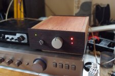
I discovered and bought my T-amp about two months ago, and decided to mod and recase it...
I just finished my mod (SI T-amp plus PSU recasing) two days ago, and this thread gave me lots of good info...
In short, to answer your question, yes, I did it... I put a PSU I had at hand into the box with mine....
Another goal was to use as much "recycled" components as possible (you know, there's a recession going on 🙂)....
So, what I managed to find was an old external (powered) disk enclosure - it had a perfect PSU - 12V, 3A, and I decided to use that. Another plus was it already had extra connectors for a fan and some LEDs.
The wiring is awful - and most of the wires are also recycled from old DVD players, VCR's, etc... 🙂
The only things I actually bought for this mod are the LEDs and the speaker binding posts (about $7-$8 total....) I had the wood at hand....
The pot and the switch on the front are from an old tape deck I got at a yeard sale for about $4 - and the pot turned out to be an old Alps 50K x2 - just what the doctor ordered!
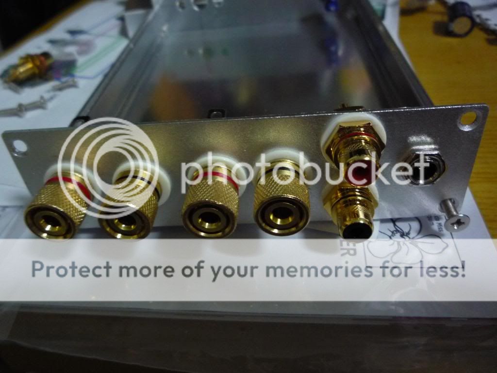
I also decided to add three inputs - two RCAs and one 3.5mm jack socket, just for variety's sake. The small switch on the front left is the input selector - and the green LEDs show which of the three inputs is active...
The big red LED is for the PSU, and the smaller red LED below it is T-amp's - I cut the original red LED, soldered some wires to the remaining LED "stubs" and "extended" its position to the front of the case.
In short, it was an easy beginner project. The only exception was removing the input caps and soldering bigger ones of better quality - just some caps I found locally, nothing special - I had a more experienced friend help me do the "sensitive" soldering stuff (removing the original SMD caps and soldering new ones). Even so, he managed to remove also the solder pads. Being versed in electronics more than I am, he managed to find the traces and solder the new caps' wires to appropriate points...
In short, I'm quite pleased how this turned out - it's my first DIY audio project (well, kind of.... I didn't make the amp myself - it's the stock SI T-amp, purchased from an online store for about 35 EUR).
In case you're wondering - my "Frankenstein" is that boxy woody thing in the picture 🙂 To the left is some Chinese amp I got for about $50 new in the local store (brand is some "Dynavox" thingie...). The bigger one below is a WEGA 120 amp (rebadged Sony, I'm told....).
Denis
Attachments
One pic per post rule...
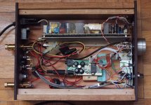
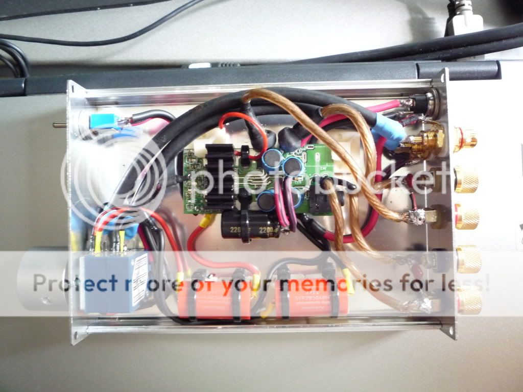
Here's the internals: don't laugh, please - I'm new at this 🙂
The PSU, like I said, comes from an external disk enclosure. Really old - it had a parallel port connection to the PC 🙂
However, it was the right size, and provides the right voltage and power (12V/3A).
I decided to avoid soldering where I could - therefore the 12V socket and jack remained intact - and the molex connector is quite visible in the photo 🙂 Laughable, I know....
The important thing, I guess, is to try to isolate the PSU from the amp - mine already had a metal (aluminum?) plate on the underside, which I turned towards the amp - see the photo... I guess it could help with the interference.
I find that putting the PSU in the box makes things less complicated. There's just one main power line that goes to wall power socket and the main switch on the back panel turns on both the PSU and the amp. I decided against a separate switch for the amp - it would make things much too complicated (two switches to turn on/off) - and I'm lazy 🙂 But, I did leave TWO LEDs: one is for the PSU, and the smaller one is for the T-amp.
As for the possible PSU to use, there are many old/broken DVD players, VCRs, etc, which usually run at 12V - so some of those PSUs can be used - 2A is a minimum, I guess... Mine has 3A. Buying a PSU on ebay is also a possibility. If you're cheap (like me), you can always find something in old electronic stuff (DVD players, VCRs, external computer disk enclosures, etc...). Besides, it's satisfying to know that you're not contributing to increased garbage footprint... Reuse, recycle.... make something new and useful from something old and discarded...😀
Attachments
i have a quick questions. i'm (almost) finishing the mod and rebox process, of which i will be posting pictures. before that, i need to know the follow:
1) How do i properly ground the board?
1) How do i properly ground the board?
Nice work Den! Welcome to the world of T-Amp fun. Looks like you found almost all the parts you need.
Now it's time for some upgrades. 😉
Now it's time for some upgrades. 😉
Nice work Den! Welcome to the world of T-Amp fun. Looks like you found almost all the parts you need.
Now it's time for some upgrades. 😉
I haven't been on the class-D forum in some time.
Glad to see you are still posting panomaniac!

ok some photos. and please help me with my questions.i have a quick questions. i'm (almost) finishing the mod and rebox process, of which i will be posting pictures. before that, i need to know the follow:
1) How do i properly ground the board?
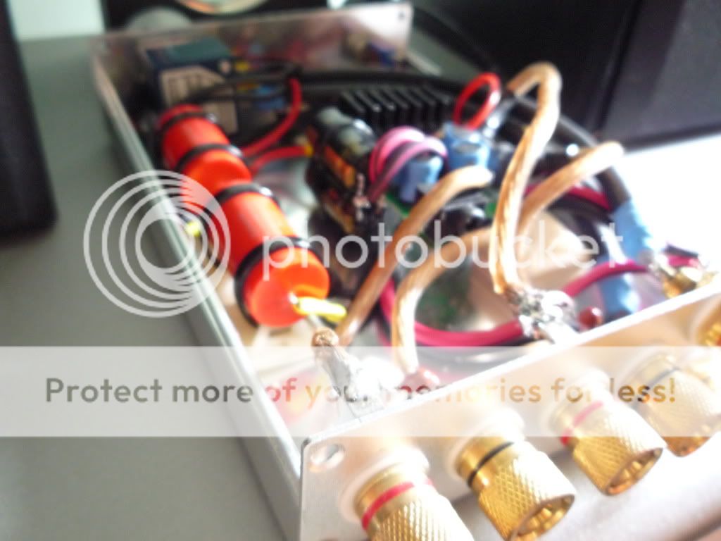
A look at what will be in the gut. A TA2024 gutted straight out of a SI5066, upsized tank cap (Elna, 2200uF), audiophiler 2.2uF input caps, alps pot, 2x white led which will light up under the volume knob, and a heatseak.
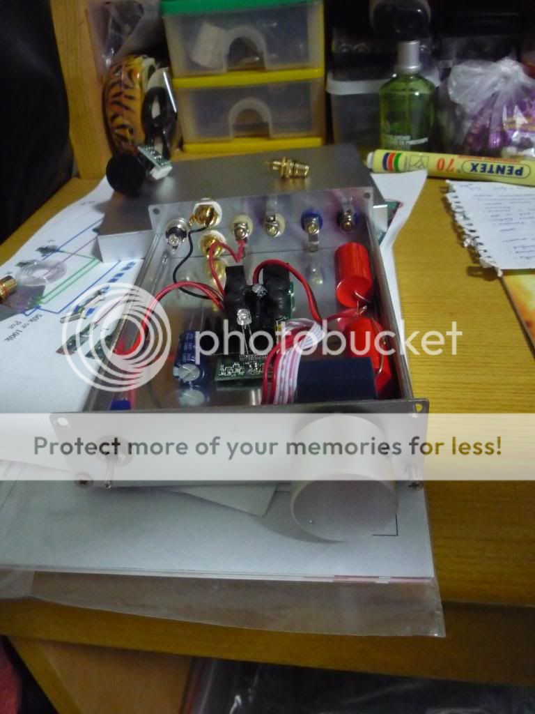
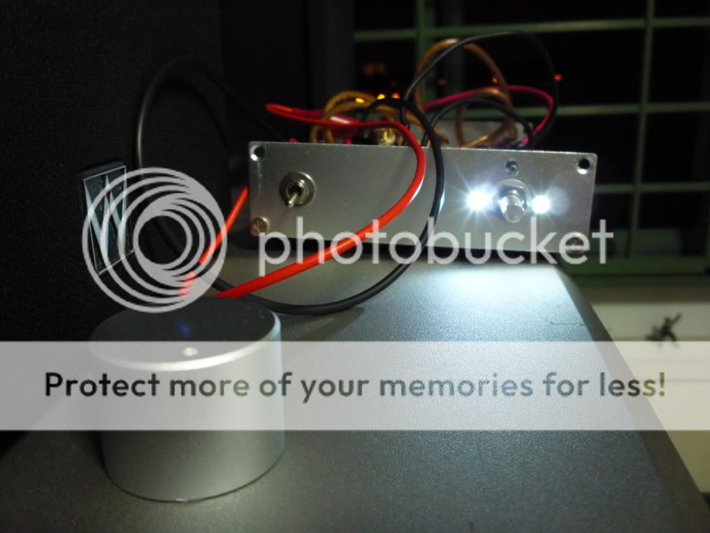
Huge volume knob.

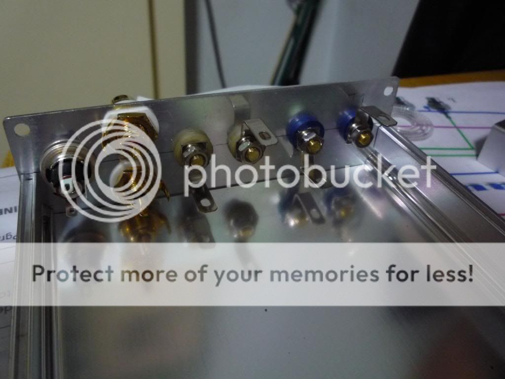
Rear mountings. Took me 1 whole day to get everything to put nicely. The drilling is a killer.
white led which will light up under the volume knob, and a heatseak.
Rear mountings. Took me 1 whole day to get everything to put nicely. The drilling is a killer.
Neat idea for the LED. Your layout & drilling came out great too!
I don't quite understand this. can anyone explain?Or just use a 75 Ohm antenna cable for each single wire in the construction. Connect the shield to its inside wire only on the "sending side" of the signal. Ex left input live will have the shield connected at the connector side, and it´s "zero" will have the shiled connected at the board side.
Much easier than building your own shield - better shield and better sound. (even if its not as good sounding as a four twinned cable).
Glad to see you are still posting panomaniac!
Thanks! I'm still around. I read but don't post much here. Don't want to stifle the creativity! There are so many good ideas here now.
And anyway, I'm up to my armpits in T-Amps already. It's not as much "fun" for me as it used to be.
I'm about done with my amp. Will post up some pictures for references soon. I did the stealth mod, and it turned out very well, except i accidentally removed a neighbouring SM cap, and it took me half an hour to find it cos i dropped it on the floor, and another half an hour to solder it back. phew. Very low static noise, nice bass gains.
But still, how do i ground the board to the casing???
But still, how do i ground the board to the casing???
I see that these 5066's are still available used on Amazon ($70 wow). I am suprised that there are still any around. I modded a few a few years ago. I have just taken an original SI out of a case so that I can use it for something else. It has the Classic mod done on it. If anyone wants it send me a PM to discuss.
Is there a place where all the mods besides classic & stealth mods are in just one list/spot (like 1 page instead of all over the place) with a link to pics (yea I'm asking a lot) I have been going over this thread of 60 + pages & the links to the other threads & pages.
Just when I think I have it all nailed down, I find some other mod that someone is trying.
I second the sentiment.
I just bought a Dayton DTA-1 amp, which is a duplicate of the original SI t-amp. And I read 60+ pages of lots of info over years. At this point, I have nothing nailed down perfectly in my battle plan either.
I don't see much reference to PSU upgrades. It seems that's the main limiter in perfomance too.
3 days of work. with all that can go wrong went wrong.
...finally it's done...
with it's trends 10.1 on top.


a look at its guts. upgraded with alps. 2 new input caps. 2xpanasonic fm (1600uF 16V). Initially i soldered 1 onto the board. it was too tall and i couldn't close the casing. it took 1 hours of surgery to get it out and put 2 by the side with all the wires set.
the volume knob led.

i wouldn't recommend such massive mods to a board so DIY unfriendly.
list of screwups:
1) accidentally ripped off a SMT cap (think it was c6).
2) ripped off the led pads, all 3 of them. led was soldered to the power terminals and switch.
3) melted the led 1k5 load resistor.
4) led leads not insulated from casing. blew 2 of them.
5) when finally everything is fixed, couldn't close the casing cause the new pana FM cap sits too high.
after so much mods, it must therefore sound nice. i think. but can't really remember how it used to sound like. nevertheless, it looks nicer now.

...finally it's done...
with it's trends 10.1 on top.
a look at its guts. upgraded with alps. 2 new input caps. 2xpanasonic fm (1600uF 16V). Initially i soldered 1 onto the board. it was too tall and i couldn't close the casing. it took 1 hours of surgery to get it out and put 2 by the side with all the wires set.
the volume knob led.
i wouldn't recommend such massive mods to a board so DIY unfriendly.
list of screwups:
1) accidentally ripped off a SMT cap (think it was c6).
2) ripped off the led pads, all 3 of them. led was soldered to the power terminals and switch.
3) melted the led 1k5 load resistor.
4) led leads not insulated from casing. blew 2 of them.
5) when finally everything is fixed, couldn't close the casing cause the new pana FM cap sits too high.
after so much mods, it must therefore sound nice. i think. but can't really remember how it used to sound like. nevertheless, it looks nicer now.
Hello,
I managed to break the input pad and C62 on a rev. D board. Does anyone ha a diagram of this board or the value for this cap? Is the stealth mod going to bypass this cap too?
Thanks.
Regards.
I managed to break the input pad and C62 on a rev. D board. Does anyone ha a diagram of this board or the value for this cap? Is the stealth mod going to bypass this cap too?
Thanks.
Regards.
- Status
- Not open for further replies.
- Home
- Amplifiers
- Class D
- Sonic Impact 5066 Parts List & Modifications