You have a 3 position switch. Probably a SPDT (single pole double throw) This page describes several different types of switches and briefly how they work. My amp actually has one of these because I had it in on hand. Just use the center pole for gnd and one of the sides for + or you could connect + to both outside poles so it would come on no matter which way you switch it.
This is another page showing how switches work.
This is another page showing how switches work.
Thanks, soundphreak!
It all makes sense now.
Now, thanks to all of you guys. You inspire me and make me want to learn and create. Thanks! Before I ask away, a little about my technical background. I have none! 🙂 I've never soldered anything in my life or know how to work a multimeter. However, I'm diving into this thing and learning fast. I own tube and solid state equipment, some mass-market stuff, and Mirage speakers. I've owned Klipsches and Magneplanar MMG's before and going back to Maggies soon. I just got my first T-amp and I am thrilled! I have a D-class 5.1 channel TEAC, as well as Motorola DCP501 on the way.
My SI T-amp board is one of the later ones, so I'm attempting Michael Mardis' "Caps Only" mod for now, until there's more info about that board. The chip is TA2024B, by the way. Now to the questions:
1. Wiring: I've seen that many of you use twisted wires for your PCB wiring. Is there a specific wire I must use? I was thinking about stripping the CAT5 wire and use the 24 gauge wires inside to twist mine. Will that work?
2. I read that TA2024B CAN be bridged, but you would have to run 2ohm speakers to see the benefits. Did I understand that correctly? And if so, are there really any practical applications for that (i.e. are there any 2 ohm speakers).
I'm sorry if I sound confusing, but you guys will set me straight, I hope 🙂
Thanks!
DIY Solar Boombox
I've been using my Sonic Impact in a solar boombox.
I've posted basic instructions here-
http://www.instructables.com/id/EYASGDSF0FI3ADK/
I've been using my Sonic Impact in a solar boombox.
I've posted basic instructions here-
http://www.instructables.com/id/EYASGDSF0FI3ADK/
Wow..cool project with the solar boom box. That was going to be project #2 for me.
I'm a total nOOb at DIY so I find myself at a hold with modifying my SI T-amp.
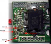
Any one have updated pictures for moding a rev. D of the SI board? I am having problems locating some of the little caps I am supposed to bridge and or remove. It's kind of good my Mardis edition Trend isn't here yet...that would give me a good excuse to give up 😉 ...but no I'm pressing on.
I'm a total nOOb at DIY so I find myself at a hold with modifying my SI T-amp.
Any one have updated pictures for moding a rev. D of the SI board? I am having problems locating some of the little caps I am supposed to bridge and or remove. It's kind of good my Mardis edition Trend isn't here yet...that would give me a good excuse to give up 😉 ...but no I'm pressing on.
Start reading this thread at about post 87 for info on the new board revisions. I have one of them also and just decided to upgrade the power circuit and re-box before this info was available. I have since built an AMP6 and am in the finishing stages of it, so I think I'll leave my SI t-amp the way it is and use my Auricaps on the amp 6.
Hope this helps
Hope this helps
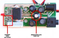
After surgery. Small delicate work.
To bridge the removed caps, use a tiny bit of L shaped wire. You hold onto one leg of the "L" with pliers or tweezers, cut off the extra after soldering.
EDIT: No need to remove the plug socket. It was done here just for illustration.
To bridge the removed caps, use a tiny bit of L shaped wire. You hold onto one leg of the "L" with pliers or tweezers, cut off the extra after soldering.
EDIT: No need to remove the plug socket. It was done here just for illustration.
Attachments

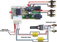
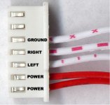
This is the new plug that connects the board to the volume pot and switch. Nice to have a plug!
Don't reverse the cable, the wires are in opposite order on each end. You will not need the last 2 wires on the right, as they come from the mini-plug and go to the pot. You will be bypassing all that, right?
You can use the red switch wires for your own switch, or just connect them together if the switch is elsewhere.
Attachments
WOW are you kidding me? This request was too easy! 😉
Awesome, Actually I am using the T-amp mod kit that was available on audiomagus for a short time...so I am in fact using the EVJ.
Hopefully they send me out your amp soon 🙂 !
Thanks a lot! Off to mod...
Awesome, Actually I am using the T-amp mod kit that was available on audiomagus for a short time...so I am in fact using the EVJ.
Hopefully they send me out your amp soon 🙂 !
Thanks a lot! Off to mod...
panomaniac said:Here are some updates on the new Sonic board.
It seems to be easier to modify than the old board. There have been some nice improvements.
Images and diagrams in the next few posts.
thanks for all the work, I may open mine back up and have a go at it.
Sorry it took so long to get done. I've been up to my eyeballs in work.
Please double check me on everything. The mods are simple, but everyone makes mistakes and errors of omission.
I do need to find a better way to illustrate the shielded cable. Maybe a dashed line for the shield? Or maybe an actual photo of the cable? Anyhow, just wire it up as best you see fit. As long as you get the right wires in the right places, you should be fine.
Panasonic Pots
A kit is available for the TA-10.1 from Audio Magus that contains the Panasonic pot. You may also purchase just the pot from DgiKey .
A kit is available for the TA-10.1 from Audio Magus that contains the Panasonic pot. You may also purchase just the pot from DgiKey .
Yeahhhh!! 😀 I think am a T-club member now!
Did all the mods per pano's directions. I'm amazed that I got any sound at all out of this thing—it's my first soldering job ever. The SMT components were a royal pain, the overall soldering job is awful...but it worked!
Sound Can't really comment on the sound yet: a) I don't remember how it sounded before the mods—it's been 5 days, b) the caps need breaking in (?). Overall, it seems that there's a little more bass in the mid-section and the highs disappeared slightly (rounded off?). Still sounds better than my AMC hybrid tube amp!
What now? Will continue breaking it in for a few days. Then will re-solder all the connections (I think I'm getting a hang of it) and house it in a RS plastic case (for now).
Questions for panomaniac (and others)
1. Why use a shielded cable?
2. What to do with the two metal (magnet?) rings around which the speaker cables are wrapped?
3. I saw many use two braided wires for all their connections. Can I braid two 24 gauge wires from cat-5 cable? Does that really make a difference?
Thanks to all for infecting me with the D-virus 🙂
samvel65 said:Yeahhhh!! 😀 I think am a T-club member now!
Good work! Welcome to the club. 😀
Questions for panomaniac (and others)
1. Why use a shielded cable?
Helps keep noise out of your input signal There is more noise inside the amp than you might think. A long run of unshielded wire can pick it up. 50Hz to 2MHz
2. What to do with the two metal (magnet?) rings around which the speaker cables are wrapped?
Those are ferrite rings to reduce the radio frequency (RF) interference going out the speaker lines. New to the Sonic. Should help FM reception if your amp is near the tuner. You can wrap your speaker wires thru them. Wrap the pair of wires together (+/-), not just one wire.
3. I saw many use two braided wires for all their connections. Can I braid two 24 gauge wires from cat-5 cable? Does that really make a difference?
Do you mean for the speaker cables? Twisted pairs are also a noise prevention technique. To keep noise in or out.
Do you mean for the speaker cables?
No, I mean the wires on PCB. I see people use a pair of twisted wires for all their connections. I guess to keep the noise to minimum.
Also, are the two small caps between L and R channel on the binding posts not necessary anymore?
Thanks for your help, pano!
I also have a Motorolla DCP501 and TEAC AG-L800 on the way. I should have my hands full 😀
panomaniac said:Here is a detail of where you will do the hard work.
I finally got around to doing this mod, it sounds much fuller now. I used jantzen 2.2 caps instead of springing for the auricaps but I am satisfied.
I learned a lesson when bridging the caps on the board, I should have used wire like you said but I used solder and got too much in there and had contact with one of the resistors, it took 15-20 minutes to clean it up while being careful not to lift the resistor.
Out of curiosity, how do they build these boards with the tiny components, is it done with robotics, by hand, voodoo or child labor, does anybody know?
Thanks everyone for the info, especially panomaniac for staying with this thread.
- Status
- Not open for further replies.
- Home
- Amplifiers
- Class D
- Sonic Impact 5066 Parts List & Modifications