Re: lowpass filter questions
Take a look at this thread. I found an interesting phenomenon when I played my turntable through the t-amp.
http://www.diyaudio.com/forums/showthread.php?s=&threadid=73120&pagenumber=2
but your experience may be completely different.
frogert said:I'm interested in more details on the T-amp's lowpass filtering- Is it sufficient enough to filter out the rumble on my direct-drive turntable?
Take a look at this thread. I found an interesting phenomenon when I played my turntable through the t-amp.
http://www.diyaudio.com/forums/showthread.php?s=&threadid=73120&pagenumber=2
but your experience may be completely different.
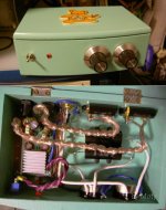
mofy said:I have modified my second T-amp.
more bass and more details 😀
thans for anyone in here.
And lots of cool...
dave
Mofy,
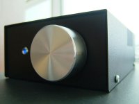
I like the way your amp looks - clean inside and kind of whimsical and comforting outside.
I really dig non-conventional chassis solutions. The look of standard black boxes can get so uninspiring.
Best,
KT
I like the way your amp looks - clean inside and kind of whimsical and comforting outside.
I really dig non-conventional chassis solutions. The look of standard black boxes can get so uninspiring.
Best,
KT
KT said:Mofy,
I like the way your amp looks - clean inside and kind of whimsical and comforting outside.
I really dig non-conventional chassis solutions. The look of standard black boxes can get so uninspiring.
Best,
KT
Thanks for everyone in here. It really helps me more.
hi, KT,
I like cute and small size style. But my first mod version has used black box too.
That one won¡¦t satisfy me. So, I finished second version 😀
Mofy
Attachments
Power switch
A question from another newbie. Thank you for your patients.🙂
When replacing the SI t-amp power /volume pot with external dittos, what is the minimum power requirement for the power switch?. I am going to place the t-amp in a recycled external CD-ROM case, and wondered if I could use the power switch already present. It is a tiny Alps switch that works by shorting a low-voltage jumper on the power board.😕
Thanks for any input. The SI t-amp mods will be my exercise; I am planning to build a Amp6 in the near future.

berthej
A question from another newbie. Thank you for your patients.🙂
When replacing the SI t-amp power /volume pot with external dittos, what is the minimum power requirement for the power switch?. I am going to place the t-amp in a recycled external CD-ROM case, and wondered if I could use the power switch already present. It is a tiny Alps switch that works by shorting a low-voltage jumper on the power board.😕
Thanks for any input. The SI t-amp mods will be my exercise; I am planning to build a Amp6 in the near future.
berthej
The T-amps don't draw much current under normal conditions. But I think a 2A switch should be minimum. Many micro switches handle up to 6A.
You can always try the tiny switch you have. What have you got to lose? Just a tiny switch that might burn out. But a nice little mini toggle switch would serve you better.
You can always try the tiny switch you have. What have you got to lose? Just a tiny switch that might burn out. But a nice little mini toggle switch would serve you better.
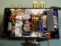
finally... thanks to one great guy, my SI is now officialy modified. I am sure, it is the first modified SI in Lithuania. lol. Here are the pics.
Now it sounds GREAT. a huge improvement. however, the highs sound a bit annoying and sharp. I suppose it due to the fact that the caps are new... and need some time to reveal. I wonder how long🙂
btw, thanks to you all, especially pano, for answering my rather stupid questions🙂
Now it sounds GREAT. a huge improvement. however, the highs sound a bit annoying and sharp. I suppose it due to the fact that the caps are new... and need some time to reveal. I wonder how long🙂
btw, thanks to you all, especially pano, for answering my rather stupid questions🙂
Attachments
output inductors DIY
Can anybody give info on winding 10uH toroid output inductors for t-amp - core size, wire size, no turns, etc.
Preferably for cores available from RS components
I tried searching here but no info - search on the web is confusing
Thanks
John
Can anybody give info on winding 10uH toroid output inductors for t-amp - core size, wire size, no turns, etc.
Preferably for cores available from RS components
I tried searching here but no info - search on the web is confusing
Thanks
John
Can anybody give info on winding 10uH toroid output inductors for t-amp - core size, wire size, no turns, etc.
Have you tried the free inductor design software at micrometals? - http://www.micrometals.com/software_index.html. It gives you everything you want and more!
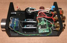
I bought the ones at jameco - 10 uH Inductor. And yes, they will fit on the board - with a little finesse 🙂
-Ken
irss said:finally... thanks to one great guy, my SI is now officialy modified. I am sure, it is the first modified SI in Lithuania.
Congratulations on the fist Modded T-amp in the country!
But you need to unplug it RIGHT NOW!
If I read your photo correctly, you have put the input caps Before the pot. Yikes! The need to be after the pot. The way it appears to be connected you will get massive DC offset and ruin your amp and maybe your speakers. Won't sound very good, either.
Please check you wiring and report back. If the amp is wired up the way I think it is, you will be able to measure DC volts on the speaker terminals.
Sorry to panic you, but I don't want you to burn it up, and it looks wrong in the photo. Pleeeease check.

At first glance, it seems he wired it funny, but under closer inspection, you can see that his wiper lug for the pot goes to the cap. Good catch, and your helpfulness is always appreciated.
Michael, do you recommend those toroids from jameco? It seems their current capacity is way oversized. That may be a good thing.
How much "finesse" do you need to put them on the board? You mean like standing them off from the board and canting them outward? Finesse doesn't seem like the right word when I think about that...
panomaniac said:
Congratulations on the fist Modded T-amp in the country!
But you need to unplug it RIGHT NOW!
If I read your photo correctly, you have put the input caps Before the pot. Yikes! The need to be after the pot. The way it appears to be connected you will get massive DC offset and ruin your amp and maybe your speakers. Won't sound very good, either.
Please check you wiring and report back. If the amp is wired up the way I think it is, you will be able to measure DC volts on the speaker terminals.
Sorry to panic you, but I don't want you to burn it up, and it looks wrong in the photo. Pleeeease check.
pano, thanks for the concern🙂
Since it was not me, who had modified the t-amp, I have no clue what could be the problem. But I should tell you that I've been listening t-amp for 5 days now, and it sounds very nice. furthermore, it seems that it sounds better and better with every day due to the 'burn-in' period of caps.
however, i refered your concern to the guy who have modified it for me. Hopefully, I will get the explanation from him and post it here.
I looked at the photo again. I'm sure that it is wired wrong. You can see the input wires coming from the RCAs to the caps, then to the pot, then to the board. That puts the pot on the wrong side.
However, I can't tell from the photo (need to look harder) if the stock input caps were removed. If there were not, then no DC offset - but --- no benefit from the new caps.
However, I can't tell from the photo (need to look harder) if the stock input caps were removed. If there were not, then no DC offset - but --- no benefit from the new caps.
hmmm...so, if it is wired wrongly, there should be a problem with the sound. but, there is no problem. i am lost completely🙂
btw, original caps were removed.
btw, original caps were removed.
Yeah, I looked closely - you can see the caps have been removed and bridged, as well as R01 removed. Good.
The way it is connected may work, but I'll bet your chip gets plenty hot. Please have a look at the DC offset to see if it is not high. You can do that with any DC voltmeter. You should not see over 1/10 volt. Anything more indicates a problem.
Let me know.
The way it is connected may work, but I'll bet your chip gets plenty hot. Please have a look at the DC offset to see if it is not high. You can do that with any DC voltmeter. You should not see over 1/10 volt. Anything more indicates a problem.
Let me know.
How much "finesse" do you need to put them on the board? You mean like standing them off from the board and canting them outward? Finesse doesn't seem like the right word when I think about that...
Finesse = Skill or Skillful*
* from dictionary.com http://dictionary.reference.com/search?q=finesse 🙂
I should have elaborated more. The hardest part of installing those BIG inductors was using the solder sucker to remove as much solder as possible - and you know how delicate the traces are. The leads on the inductor will fit the holes, but it's a close fit.
Michael, do you recommend those toroids from jameco? It seems their current capacity is way oversized. That may be a good thing.
These are the smallest ones I could find. Someone else on the board mentioned these from Jameco. Plus, I think the ones that 41hz.com (Amp3 kit) uses are about the same size - see pic

-Ken
holy cow you're right. it is wired wrong-way-round. Hopefully he hasn't damaged his drivers.
Finesse: not what phil has.
so the leads are the problem? stink. Maybe a toroid with a closer current capacity to what is needed would shrink the leads. Anybody found some?
Finesse: not what phil has.
so the leads are the problem? stink. Maybe a toroid with a closer current capacity to what is needed would shrink the leads. Anybody found some?
- Status
- Not open for further replies.
- Home
- Amplifiers
- Class D
- Sonic Impact 5066 Parts List & Modifications