And how about 3 Output Pairs. What will be the max. rail voltage in this case?The two pair 'Mini' I'd suggest a max supply of +/-52V rails and it could deliver up to 150W with a good rigid PSU and perhaps a boosted (+5V) set of rails for the IPS to maximize output.
Hi vargasmongo3435, Vrystaat and still4given,
Thanks for sharing your experience with different IPS stages 🙂
Could you please share the layout in pdf format of the IPS which you have built. That would really help me.
Regards,
Sha
Thanks for sharing your experience with different IPS stages 🙂
Could you please share the layout in pdf format of the IPS which you have built. That would really help me.
Regards,
Sha
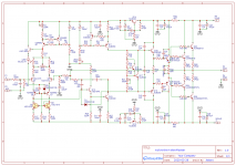
And Please, when ever you post a PCB layout, please post the corresponding circuit diagram also by the side !
Hi vargasmongo3435, Vrystaat and still4given,
Thanks for sharing your experience with different IPS stages 🙂
Could you please share the layout in pdf format of the IPS which you have built. That would really help me.
Regards,
Sha
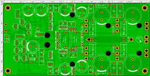
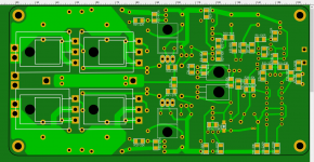
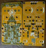
Here are the PDF files for the Spooky version that I built. Please note that it is a double sided board.
Hari
Attachments
Here are the iron transfer files that I used to build the Wolverine, Spooky and Kypton ND.
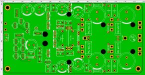
On the Spooky/Leach there is one jumper that is not used. I have added the silk showing which jumper to leave off.
Good luck, Terry
On the Spooky/Leach there is one jumper that is not used. I have added the silk showing which jumper to leave off.
Good luck, Terry
Attachments
-
 494272d1437247282-slewmaster-cfa-vs-vfa-rumble-ndbest.jpg152.4 KB · Views: 889
 -
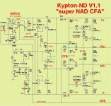
Kypton ND foil Terry.pdf188.4 KB · Views: 185
-
Kypton ND silk.pdf87.6 KB · Views: 198
-
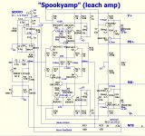 Spooky-V1.2-schema.jpg166.7 KB · Views: 873
 -
Spooky mirror print file.pdf255.7 KB · Views: 245
-
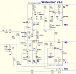 Wolverine-V1.2-schema.jpg123.3 KB · Views: 855
 -
wolverine-C-V1.2 X-man iron transfer.pdf136.1 KB · Views: 260
-
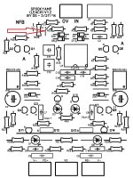 Bad jumper.jpg249.1 KB · Views: 822
Thank you Hari and Terry for sharing the files.
Hope the spookyamp layout shared by both of you refers to V1.2.
Thanks again 🙂
Reagrds
Sha
Hope the spookyamp layout shared by both of you refers to V1.2.
Thanks again 🙂
Reagrds
Sha
Thank you Hari and Terry for sharing the files.
Hope the spookyamp layout shared by both of you refers to V1.2.
Thanks again 🙂
Reagrds
Sha
Yes it is the V1.2.
Hari
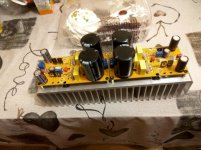
this is a good enough wiring wolverine+Sewmaster or I need to twist the details
On one Board made because of one transformer, I'm afraid that otherwise there will be a low-frequency background hum
what ultimately the better amplifier - The "Honey Badger" or Wolverine+SlewМaster
On one Board made because of one transformer, I'm afraid that otherwise there will be a low-frequency background hum
what ultimately the better amplifier - The "Honey Badger" or Wolverine+SlewМaster
Attachments
Last edited:
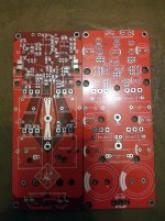
why, if the earth is the whole layer and everything on the board is wired correctlyNo lifted ground on the input?
It's uses are:
To prevent possible ground loops from the source.
To prevent possible ground loops within the amp.
It may lower the ground noise.
Unless you have a prototype board you will not know if you will have the above problems.
Hope that helps.
PS you can always put in a wire link, later, instead of the resistor.
Last edited:
why, if the earth is the whole layer and everything on the board is wired correctly
Most preamps or other sources will use a common ground for both channels. If you are building a stereo amplifier that has the power supply grounds connected together it will set you up for ground loop issues. The diodes and resistor of the ground loop will stop current flow through the interconnect cable screens. The few ohms resistance added to the input impedance are really irrelevant. Cheap insurance.
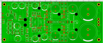
well, i can always connect the ground of this Board (which is laid out earlier) to the power supply Board by resistors in 5-10 ohms
But on the boards apex-14,17 and 20, that already collected and listened to it was not necessary.
But on the boards apex-14,17 and 20, that already collected and listened to it was not necessary.
Attachments
Last edited:


- Home
- Amplifiers
- Solid State
- Slewmaster - CFA vs. VFA "Rumble"