I am only a mechanic..all the credit goes to the awesome members here.
I plan dual mono with 2 600VA 58 vac transformers and crc cap banks 27000uf-r075-27000uf. Should do the trick.
Evan
I plan dual mono with 2 600VA 58 vac transformers and crc cap banks 27000uf-r075-27000uf. Should do the trick.
Evan
So we are running "monsters" With verticle FETS while jumpering the
predrivers ... interesting.
5 pair IRFP's .... wow! 600W + amps.
OS
That is an option I was mulling over at the same time as vzaichenko was. He put together the first one and we worked out adding the LED and bias generator values to Taylor tempco to suit the MOSFETs. The boards adapt to vertical MOSFETs very easily and it works just fine.
Absolutely terrific build Quan. May I ask where you found those large flanged M3 washers you've used on the outputs? I've been looking high and low for those.
Mate, i got them from fleabay awhile back. I guessed lucky dip.
Quan
That is an option I was mulling over at the same time as vzaichenko was. He put together the first one and we worked out adding the LED and bias generator values to Taylor tempco to suit the MOSFETs. The boards adapt to vertical MOSFETs very easily and it works just fine.
http://www.diyaudio.com/forums/solid-state/43331-power-amp-under-development.html
One of my first DIYA experiences ,Vertical mosfet madness .
brings back memories.
From that thread , I remember that the IRF's are not that linear near
the X-over point .
Biasing hotter brought better sound but for flat out RAW power , any
bias (even under-biasing) would do.
"quasi" (member) used one MJE350 ( a standard EF2 Vbe) for thermal
stability.
He also ported his FET design to a BJT offering , this was the preferred
version for the "picky" builders.
The laterals were never discussed , but they are reported to be the
best of both worlds (power vs. sound quality).
OS
I build the two version from quasi :
-The Nmos 200 with one paire IRF460 : mnos-200 - audiyofield
-The Nbip with 3 MJL3281 pairs : nbip-100 - audiyofield
Both are really good sounding amp with an advantage to BJT version as you said but both are not at VSSA or Versatil (BJT VSSA version) level.
Marc
Just thought I would share my first influences with the forum.
The "slew" series has the quasi , frugalamp , supersym , badger
experiences all combined. The design was meant to be open
to progressive improvements.
I'm still learning more every day (slewmaster main thread), we are way past "consumer" level ...
I think we are getting closer to "lower high-end" , as far as the designs
go.
With soon to be developed protection/PSU ... accessories 😀 ....
No reason to not to exceed so- called "audiophile" offerings. 😀
OS
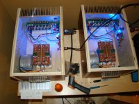
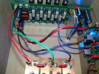
The DC offset is good both channels 5mV. Here are some pictures of the toroid arrangements.
I am please to report such excellent sound from the amp. You guys are in for a real treat to build this amp.
The DC offset is good both channels 5mV. Here are some pictures of the toroid arrangements.
Very clean build. Beautiful!

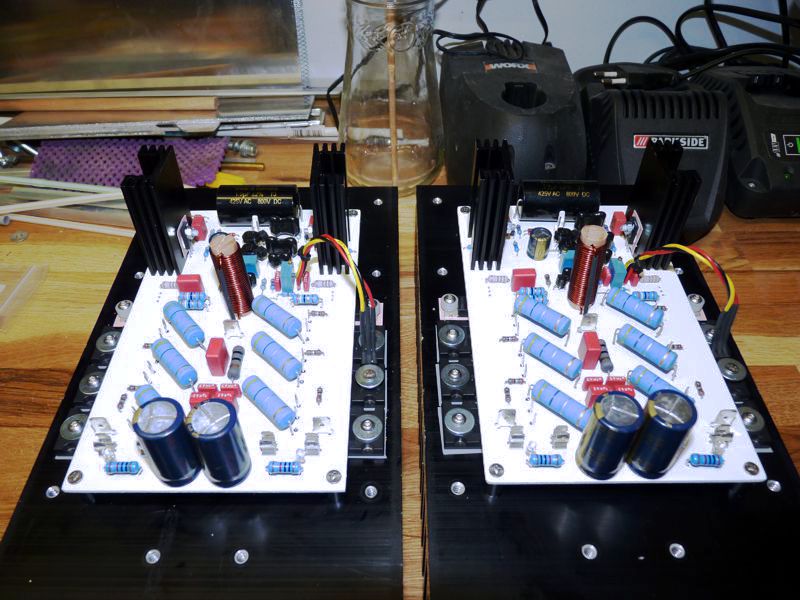
Here are some shots of my first channel. +- 60Vdc. Bigger 58 vac. transformers are on the way. Mosfet 240/9240outputs. Seems to work right from start up. Offset can be set at or near zero. Bias cold is 53 mA and dropped to 50mA after playing for about half an hour. The heatsink was barely warm. Now for the second channel and a real listen.
Thanks to all, Evan
I'm still running this setup with 3 pairs of IRFPs on my test bench, with tube IPS and NO GNFB! - like it a lot

This amp will be running just woofers. I will build a second one with bjt outputs to drive the tops after.
I am seeing a lot of interest in the little "mini OPS" in the group buy thread. Is that the little lateral OPS we worked out? If so, it is basically a <+-50V unit. I was able to use it fine with the CFA-HX IPS but another balked at the lower voltage. Can someone suggest the resistor changes that could be use in each of the present IPS boards so they work optimally at the lower rails?
Blessings, Terry
Blessings, Terry
That's why my amps have them.The laterals were never discussed , but they are reported to be the best of both worlds (power vs. sound quality).
OS

Hi MarcBoth are really good sounding amp with an advantage to BJT version as you said but both are not at VSSA or Versatil (BJT VSSA version) level.
Marc
You should test FO v1.3 and hear what this topology is capable of. 😉
Basically the 12V shunt regulators don't like the lower voltages with the originally prescribed voltage dropping resistor values. The issue is that shunt regulation relies on a certain amount of current to flow through the regulating element, a zener diode in our case, for reliable regulation to occur. For <50V rails those resistors may need to be a fair bit lower in value to get good solid regulation re-established. The ideal value is dependent upon the rail voltages being used. These resistors would be:
CFA-XH, R13 and R14
Symasui, R11 and R13
Wolverine, Doesn't have any shunt regulators 🙂
Spooky, R23 and R24
etc...
To calculate you take your planned rail voltage, subtract the zener voltage (generally 12V units are used) and use Ohm's law to calculate the ideal resistor value that gives about 10-12mA of current flow through the resistor. Example:
A builder wants a relatively low power Mini OPS build and plans on +/-36V rails. So, 36V-12V leaves 24V to be dropped over the resistor. We want 12mA of shunt regulator current which means the resistance according the Ohm is 24V/12mA resulting in a 2K0 resistor being specified. In this case 2K2 might be more common and would work just fine.
Does that help?
Last edited:
Hi Jason,
Yes that was the answer I was looking for. I thought it would be useful for all those who are buying and planning to build using this little jewel.
Blessings, Terry
Yes that was the answer I was looking for. I thought it would be useful for all those who are buying and planning to build using this little jewel.
Blessings, Terry
Terry, your amp portfolio keeps growing and I was wondering if your honey badger is still your favorite. I seem to recall briefly reading someone working on sub-ppm distortion throughout the audio band amp, was that Valery? If you recognize this amp project could you point me to it?
Here are a couple shots of my build. 5 pair 240/9240 +-80volt. I had planed on using it just for woofers, but ended up liking it running the midranges and tweeters.
I'm working on a 5 pair bjt output set and have a couple questions.
For mjw 1302/3281 outputs do you guys like the same as the output for drivers or I could use fairchild fjl43150/42150. https://www.fairchildsemi.com/products/discretes/bipolar-transistors/high-power-bjts/FJL4215.html
For matching the bjt outputs is it the same as matching mosfets?
Thanks for helping a simple mechanic, Evan
Attachments

The Fairchild parts should be just fine for the drivers. I like the ON Semiconductor and Fairchild parts, so you can take your pick. The drivers of course only need to be in the TO-3P / TO-247 size package, so the FJA4213 / FJA4313 fit the bill nicely.
The matching is less critical with BJT devices, they will be closer to one another than MOSFETs typically are and current sharing tends to be more even. You can of course still match them, Vbe and Beta, if you like but it shouldn't be required.
The matching is less critical with BJT devices, they will be closer to one another than MOSFETs typically are and current sharing tends to be more even. You can of course still match them, Vbe and Beta, if you like but it shouldn't be required.
Thanks for the advice. I have all my parts on hand and hope to have another working pair of amps in the next couple weeks...I'm not nearly as fast as some here are.
E
E
I forgot to mention you have a nice looking implementation. What did you choose for your main heat sinks? Are those HeatSink USA extrusions?
- Home
- Amplifiers
- Solid State
- SlewMaster Builds