Not a bad idea for an actual listening test of an IPS though prior to meeting a proper OPS. Requires almost no parts.
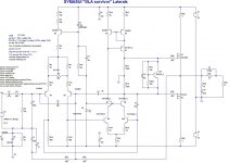
OK, I added a VBE and removed the diodes. I runs nice in spice. The overall THD is quite low but looks like H2-H4 are higher than usual. Maybe I'm reading it wrong.
Harmonic Frequency Fourier Normalized Phase Normalized
Number [Hz] Component Component [degree] Phase [deg]
1 2.000e+04 1.214e+00 1.000e+00 -0.01° 0.00°
2 4.000e+04 9.271e-07 7.637e-07 -6.00° -5.99°
3 6.000e+04 3.310e-06 2.726e-06 -85.88° -85.87°
4 8.000e+04 3.602e-07 2.967e-07 -169.61° -169.60°
5 1.000e+05 2.347e-06 1.933e-06 -82.65° -82.64°
6 1.200e+05 2.919e-07 2.404e-07 -161.26° -161.24°
7 1.400e+05 1.626e-06 1.339e-06 -78.99° -78.98°
8 1.600e+05 2.752e-07 2.267e-07 -157.76° -157.75°
9 1.800e+05 1.180e-06 9.717e-07 -75.89° -75.87°
Total Harmonic Distortion: 0.000383%
Anyway, please have a look and maybe run the spice file and let me know what you think. Looks like it would be fun to put together a really small OPS to have fun with.
Blessings, Terry
Attachments
Last edited:
Make R31 and VR32 higher in value, something like 2K2. At 100R most of the bias current is going through those and the transistor isn't doing much. Vary VR32 until you get about 100mA of idle current.
R24 and R25 can be lower too, perhaps as low as 100R.
I will take a closer look in an hour or two.
R24 and R25 can be lower too, perhaps as low as 100R.
I will take a closer look in an hour or two.
Terry, I found a few errors. Try out this file. I put models from my collection in just for my convenience and put them right into the LTSpice file. The variable resistor in the real VBE multiplier would be a 5K pot near its middle.
EDIT: Which post did you find that schematic in? The 'final' one in the GLA thread looks nothing loke the one you posted in the spice sim.
EDIT the EDIT: Never mind, found it!
EDIT: Which post did you find that schematic in? The 'final' one in the GLA thread looks nothing loke the one you posted in the spice sim.
EDIT the EDIT: Never mind, found it!
Attachments
Last edited:
Hi Jason,
I thought the schematic I used matched the one for the boards you made the layout for. If not can you tell me which one you used so I can make sure it will work?
That file runs nice but even with 20K in VR I couldn't get the bias down to 100mA. The error log shows low THD but the harmonic profile is not so great. Still, if I can figure out how to keep the bias to a reasonable level I would like to try it. Any idea why it sims so high?
Thanks, Terry
Build thread
I fell into the trap. This probably should be in the main development thread. I'm OK with discussing this here rather than the main thread only because this has the potential to become another IPS option that is distinct from the others. If it gets really 'out there' and drags the thread away from a builds then some housekeeping may need to be done to have the posts moved to the main thread.
I fell into the trap. This probably should be in the main development thread. I'm OK with discussing this here rather than the main thread only because this has the potential to become another IPS option that is distinct from the others. If it gets really 'out there' and drags the thread away from a builds then some housekeeping may need to be done to have the posts moved to the main thread.
Hi Jason,
I thought the schematic I used matched the one for the boards you made the layout for. If not can you tell me which one you used so I can make sure it will work?
That file runs nice but even with 20K in VR I couldn't get the bias down to 100mA. The error log shows low THD but the harmonic profile is not so great. Still, if I can figure out how to keep the bias to a reasonable level I would like to try it. Any idea why it sims so high?
Thanks, Terry
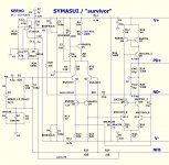
The asc file you posted had the N and P MOSFETs reversed. Which layout are you referring to? Symasui?
Sorry, I didn't mean to change the IPS. I thought I was using the correct Schematic. I thought it would be ok here because I want to use my Symasui IPS and probably my CFA-XH boards with it. The same ones you are selling. Please give me the schematic you did the layout from and I will use that.
Thanks, Terry
Thanks, Terry
No problem. The GLA is a prior iteration to the Symasui. The attached schematic is what the Symasui boards are based on.
Attachments
Last edited:
Well not so different after all. The earlier iterations were just drawn differently and some features changed or added. I got all the different versions mixed up. My apologies.
Arrg,
I did the best I can but just can't get it to work. Maybe you can take a look when you have time. I added KSA1015 to the list since that is what OS used. Not sure if my model is correct so you may want to look there first. If you thinks the guys here who are buying the Symasui boards will not be interested in this I will be happy to take it to the other thread.
Thanks, Terry
Attachments
Terry,
Keep going it is just another version of the slewmaster. I like that you find new problems and solutions, it is helpful to just read all of this.
Keep going it is just another version of the slewmaster. I like that you find new problems and solutions, it is helpful to just read all of this.
Hi Bimo. I am fixing up the amp so no in depth listening as yet. Apparently the all the fuses blown took out the diodes /rectifier- must be a short some where. Initial listening is crystal clear highs and transparent.😎
How about the sound?
Quan
Arrg,
I did the best I can but just can't get it to work. Maybe you can take a look when you have time. I added KSA1015 to the list since that is what OS used. Not sure if my model is correct so you may want to look there first. If you thinks the guys here who are buying the Symasui boards will not be interested in this I will be happy to take it to the other thread.
Thanks, Terry
Q3 and Q4 are KSA992, not KSC1845. Runs after correcting device choice. You have the correct symbol (PNP), wrong part (NPN). Also name the node where the MOSFETs join as vout so you get the fourier (THD) of the output, your THD was for the input node. The output THD, as it would be expected, is vastly higher. An EF buffer might help, but then we go adding complexity back into the mix.
Last edited:
Hi Bimo. I am fixing up the amp so no in depth listening as yet. Apparently the all the fuses blown took out the diodes /rectifier- must be a short some where. Initial listening is crystal clear highs and transparent.
Quan
What happened? Rectifier in the power supply or a damaged OPS?
What happened? Rectifier in the power supply or a damaged OPS?
I think one of the stray stranded of wired across the power supply caps that caused the damage. It took out the bridge rectifier, all the fuses, and the diodes in the OPS but luckily all trannies are ok so all fixed now.
Quan
I think one of the stray stranded of wired across the power supply caps that caused the damage. It took out the bridge rectifier, all the fuses, and the diodes in the OPS but luckily all trannies are ok so all fixed now.
Quan
Glad to hear you got it sorted. The rail-to-ground diodes are there to hopefully catch a builder's error or PSU failure. You just proved their worth; unfortunate for you, good for the rest of us. A couple of cheap rectifier diodes likely saved the rest of the OPS.
- Home
- Amplifiers
- Solid State
- SlewMaster Builds