I am populating my cfa xh 1.3 boards....where is it advisable to use the larger to92L devices?
Thanks, Evan
Thanks, Evan
I thought I recalled someone mentioning that at higher rail voltages the input pair would be close to max dissipation. I have some 916 /2316 parts I could use.
The input pair dissipation should be OK. I think under normal use or even test scenarios you likely won't find any issue. If you have devices that are hardier, high beta types then by all means use them. Match the beta as best you can and watch device pinout when substituting.
another parts selection question that may seem silly to more knowledgeable parties. for the cfa-xh ips what part of rail voltage do c7/8 see?
another parts selection question that may seem silly to more knowledgeable parties. for the cfa-xh ips what part of rail voltage do c7/8 see?
In the simulator, those see less than a volt. I would think 16V would be enough. I thinks there is a BOM for that somewhere but I don't seem to have it. Hope this helps.
Blessings, Terry
another parts selection question that may seem silly to more knowledgeable parties. for the cfa-xh ips what part of rail voltage do c7/8 see?
C7 and C8 see almost no significant voltage. They can be 6V3 parts.
Hi guys, just a question re bulb limiter. Should i only use to start up first build amp to ensure it is ok but not to use it when adjusting the bias?. I finally put my 5OPS into a case but one chanel offset is 1mV but the other is 22mV so i have to remove it from chassis to adjust bias again. I have read somewhere re not to use bulb limiter when adjusting the bias thus just want to clarify it.
Quan
Quan
Some settings can be sensitive to the somewhat reduced rails when using the bulb limiter. I generally do my basic functional tests with the limiter and final adjustment without it.
Some settings can be sensitive to the somewhat reduced rails when using the bulb limiter. I generally do my basic functional tests with the limiter and final adjustment without it.
Thanks Jason.
Hi Jason, I am finally boxing 5OPS/CFX IPS- one of the channel I could not get the bias to stabilised-drifting btw 16mV-16.5mV across RE, the other channel bias is rock solid. I also noticed that the transformer has a bit of buzz to it and the cycle of buzz cause the bias to fluctuate?.
Quan
Quan
Have you tried swapping the IPSs to see if the issue (a really minor issue, might even be related to a radiated field in the case) follows the IPS? Really that bias fluctuation is only on the order of 2-3mA, so isn't likely a genuine issue. Does it sound OK?
If it is a radiated field and you are using a torrid you might be able to just rotate the transformer to find a spot the perturbs the surrounding circuitry the least. Also make sure no hardware creates a 'shorted turn', this will make a transformer buzz too.
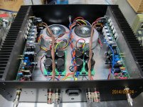
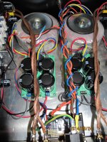
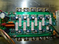
Post a picture of the current arrangement so we can visually check the assembly.
If it is a radiated field and you are using a torrid you might be able to just rotate the transformer to find a spot the perturbs the surrounding circuitry the least. Also make sure no hardware creates a 'shorted turn', this will make a transformer buzz too.
Post a picture of the current arrangement so we can visually check the assembly.
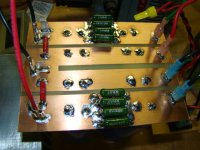
Absolutely terrific build Quan. May I ask where you found those large flanged M3 washers you've used on the outputs? I've been looking high and low for those.
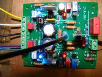
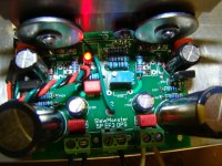
Here are some shots of my first channel. +- 60Vdc. Bigger 58 vac. transformers are on the way. Mosfet 240/9240outputs. Seems to work right from start up. Offset can be set at or near zero. Bias cold is 53 mA and dropped to 50mA after playing for about half an hour. The heatsink was barely warm. Now for the second channel and a real listen.
Thanks to all, Evan
Thanks to all, Evan
Attachments
- Home
- Amplifiers
- Solid State
- SlewMaster Builds