
I'm just now beginning to learn how to use the Quasimodo myself.
With that said, I think if you set your trigger to the falling edge, you'll get something more closely resembling the examples in Mark's guide.
Awesome!
With that said, I think if you set your trigger to the falling edge, you'll get something more closely resembling the examples in Mark's guide.
Awesome!
You are looking at the right thing.
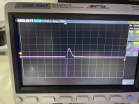
The 2nd trace is too damped… adjust the pot to match this example-

The 2nd trace is too damped… adjust the pot to match this example-
Hi, new Quasimodo user here. I am also quite new to using oscilloscopes. So I am trying to dial in a Triad VPM18-2780. I shorted as follows and I am measuring BLK/RED:

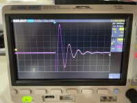
This is the undampened trace:

With Cx=10nF, Cs=0.1uF and Rs=11R I get:

Zooming in, this looks like:

There is hardly any difference between Cs=0.1/0.15...0.27uF.
Questions:
This is the undampened trace:
With Cx=10nF, Cs=0.1uF and Rs=11R I get:
Zooming in, this looks like:
There is hardly any difference between Cs=0.1/0.15...0.27uF.
Questions:
- I just can't get a steadily decining curve after the positive peak (3rd picture), and the decline to base line takes longer than it should compared to the traces in the manual (2nd pic). Still, this now looks overdampened. If I increase Rs I get a wave on the decline. Thoughts?
- Is the low Rs a problem?
@maximax77
The with snubber trace you’ve posted is a LOT better than the no snubber trace, so you are making improvement.
Don’t worry too much about the C value, as the R is what is actually doing the snubbing. I don't think I’ve ever used a R bigger than 33 ohm even on a small transformer, and on power transformers the typical value is 10-15ohm… which is to say you are doing it properly.
🙂
I did run into a small transformer out of a Technics SL-D3 turntable that took over 500ohms. Don't remember the exact resisitor value I used, but had to switch to a 1k pot to find the right value.@maximax77
The with snubber trace you’ve posted is a LOT better than the no snubber trace, so you are making improvement.
Don’t worry too much about the C value, as the R is what is actually doing the snubbing. I don't think I’ve ever used a R bigger than 33 ohm even on a small transformer, and on power transformers the typical value is 10-15ohm… which is to say you are doing it properly.
🙂
Apologies for going on a tangent, but pursuing Mark’s suggestion in this thread from many years ago I am wondering which filter curve is preferable for a power supply for a streamer. The datasheet, the relevant options:another fruitful path of exploration might be EMI/RFI filters between the AC mains and the transformer primary here is a datasheet
FN2090-1-06
FN2090KK-1-06
The standard version (first chart) performs better at higher frequencies, the enhanced version is better at lower frequencies. Many thanks in advance for any thoughts on this.
Hello everyone!
Almost finished my Quasimodo V4 board assembly. Some parts are missing but I tested LMC555 oscillation and it works 🙂 My question is about oscillator frequency. With resistor R3 (39K) it is set to about 120Hz and with DIP switch you can increase it. When these higher frequencies are used? And if I am living in 50Hz world should I set this frequency to 100Hz and use 47.6k resistor instead of 39k?

Almost finished my Quasimodo V4 board assembly. Some parts are missing but I tested LMC555 oscillation and it works 🙂 My question is about oscillator frequency. With resistor R3 (39K) it is set to about 120Hz and with DIP switch you can increase it. When these higher frequencies are used? And if I am living in 50Hz world should I set this frequency to 100Hz and use 47.6k resistor instead of 39k?
See posts # 1214 , 1303 , 1145 , and 1165 of this thread. Also see post # 14 of the Cheapomodo thread .
lookup words to help me find this post in the future:
switch 50Hz 60Hz 100Hz dim 120Hz 50 Hz 60 Hz 100 Hz 120 Hz analog CRT scope DIP DIPswitch sweep frequency duty cycle
lookup words to help me find this post in the future:
switch 50Hz 60Hz 100Hz dim 120Hz 50 Hz 60 Hz 100 Hz 120 Hz analog CRT scope DIP DIPswitch sweep frequency duty cycle
Thank you and I am sorry to ask a question that was answered already. The thread is quite long and I did not found an answer in first 50 pages. Now it is more or less clear. And thank you again for sharing your experience. Some people do not like that novice are asking dummy questions but without it forum probably will not exist...
First tests:

Without Rs, Cs=0.15uF, Cx=0.01uF:

Rs=540R, for 230V 0.1mA secondary and for 6.3V 2.5A secondary Rs=15R. But it was very quick tests and probably I need to repeat it. But happy that board is working 🙂

And transformer:

PCB's were ordered from JLCPCB with Gerber files attached by Mark Johnson. If somebody needs I have few spare PCB's.
Without Rs, Cs=0.15uF, Cx=0.01uF:
Rs=540R, for 230V 0.1mA secondary and for 6.3V 2.5A secondary Rs=15R. But it was very quick tests and probably I need to repeat it. But happy that board is working 🙂
And transformer:
PCB's were ordered from JLCPCB with Gerber files attached by Mark Johnson. If somebody needs I have few spare PCB's.
Very, very nice! Congratulations @Sarunas ! Your scope photo shows just about perfect damping. The second lumpity bumpity is juuuuuuust barely flat and that's the goal. Good on ya.
All, are there any Quasimodo V4 boards available for sale? Would like to purchase one.
Please let me know.
Thanks
Scott
Please let me know.
Thanks
Scott
- Home
- Amplifiers
- Power Supplies
- Simple, no-math transformer snubber using Quasimodo test-jig