It's possible that your Cheapomodo board is faulty and has no output. That would be one possible explanation for the observation of no output waveform with an oscilloscope.
For example if diode D1 is soldered poorly, or if it is installed backwards (!!) then there will be no power supply voltage for the 555 oscillator. No supply voltage means no output waveform. You can verify this with your digital voltmeter by
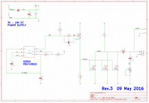
1. Measure the voltage between PWR_IN and GND (upper left of the schematic).
2. Measure the voltage between circuit node "VCC" and GND. VCC is found on pin 8 of the 555.
Both of these measured voltages should be very very close to the output of your battery or power supply. If one or both of them is low, you've found a problem.
Another possibility is that your 555 chip is faulty, or installed backwards. You can test that by connecting your oscilloscope to 555 pin 3 (circuit node "OSC") with the scope ground clip connected to circuit GND. With the vertical amplifier set to 5 volts per vertical division and the horizontal sweep rate set to 2 milliseconds per division, you ought to see a square wave on node OSC. THESE ARE NOT THE IDEAL SETTINGS TO OBSERVE TRANSFORMER RINGING !! THEY MERELY SHOW YOU THE ENTIRE LOW-FREQUENCY SQUARE WAVE ON NODE OSC.
_
For example if diode D1 is soldered poorly, or if it is installed backwards (!!) then there will be no power supply voltage for the 555 oscillator. No supply voltage means no output waveform. You can verify this with your digital voltmeter by
1. Measure the voltage between PWR_IN and GND (upper left of the schematic).
2. Measure the voltage between circuit node "VCC" and GND. VCC is found on pin 8 of the 555.
Both of these measured voltages should be very very close to the output of your battery or power supply. If one or both of them is low, you've found a problem.
Another possibility is that your 555 chip is faulty, or installed backwards. You can test that by connecting your oscilloscope to 555 pin 3 (circuit node "OSC") with the scope ground clip connected to circuit GND. With the vertical amplifier set to 5 volts per vertical division and the horizontal sweep rate set to 2 milliseconds per division, you ought to see a square wave on node OSC. THESE ARE NOT THE IDEAL SETTINGS TO OBSERVE TRANSFORMER RINGING !! THEY MERELY SHOW YOU THE ENTIRE LOW-FREQUENCY SQUARE WAVE ON NODE OSC.
_
Attachments
Last edited:

Hello, thank you very much.
Indeed, the first check I did is the power supply of the 555 being correct, what I have not checked is output number 3 of the 555.
I will carry out the checks that you have indicated and I will inform you.
Thanks to you and randytsuch, for helping me
Indeed, the first check I did is the power supply of the 555 being correct, what I have not checked is output number 3 of the 555.
I will carry out the checks that you have indicated and I will inform you.
Thanks to you and randytsuch, for helping me
Good afternoon sirs.
As you told me, Mr. Mark, I checked the output of pin 3 of 555, and indeed a square wave signal comes out as you told me, I checked the breadboard and the problem was the lack of gnd in the connections that go out to the oscilloscope.
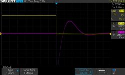
I have attached photos of a small transformer, which works fine but with different oscilloscope voltage and time bases (perhaps the bc546 is the cause of a low output signal), with CX 10nf and CS1 150nf, the resistance resulting was 90 ohms.
Another photo attached with a bigger transformer with CX 10nf and CS1 150nf and the resistance of 22ohms after the correction.
What opinion do you give me regarding the low outputs that are represented on the oscilloscope?
As you told me, Mr. Mark, I checked the output of pin 3 of 555, and indeed a square wave signal comes out as you told me, I checked the breadboard and the problem was the lack of gnd in the connections that go out to the oscilloscope.
I have attached photos of a small transformer, which works fine but with different oscilloscope voltage and time bases (perhaps the bc546 is the cause of a low output signal), with CX 10nf and CS1 150nf, the resistance resulting was 90 ohms.
Another photo attached with a bigger transformer with CX 10nf and CS1 150nf and the resistance of 22ohms after the correction.
What opinion do you give me regarding the low outputs that are represented on the oscilloscope?
Attachments
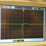
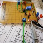
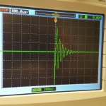
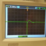

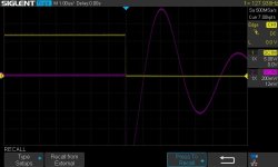
Photo #5 is just about perfect, congratulations.
Photo #2 is not perfect, you have flattened the trace too much. Go back and do #2 again until you get a waveform with one up bump and 0.1 down bumps.
Also watch some videos about oscilloscope triggering, your photo #6 has poor triggering.
Photo #2 is not perfect, you have flattened the trace too much. Go back and do #2 again until you get a waveform with one up bump and 0.1 down bumps.
Also watch some videos about oscilloscope triggering, your photo #6 has poor triggering.
Hello again gentlemen.
Thanks Mark for his unconditional help.
I have already solved the trigger problem, although I have not taken photos it works perfectly, it is an excellent device.
Once again thanks to everyone and especially to you Mark, for delighting us with this great device
Thanks Mark for his unconditional help.
I have already solved the trigger problem, although I have not taken photos it works perfectly, it is an excellent device.
Once again thanks to everyone and especially to you Mark, for delighting us with this great device
What a wonderful tool! I ordered a set of boards and completed one a couple of days ago. Spent a couple of hours measuring several different transformers, and am looking forward to using it when I redesign the PS board for one of my amplifiers. Thank you Mark for this contribution and your ongoing assistance, and to all who have helped new user/builders.
Thank you. I’ll let you if I don’t get one here in the US.I have an unpopulated spare
You could try the Swap Meet section of the diyAudio Forums.
Make a very provocative thread title, that will immediately attract attention, such as perhaps:
WANTED: Fully assembled and tested Quasimodo V.4 (thru hole), will pay USD 80 + shipping
or whatever price you are willing to offer. You might get responses, you might not, either way the cost of making an attempt is low.
also, inquire whether member @dsolodov knows of any pre-built QM boards for sale.
Last edited:
QM builders & owners:
Somebody wants to buy YOUR working Quasimodo (V.4 -- thru hole) and will pay $80 plus shipping
(Link to offer)
Somebody wants to buy YOUR working Quasimodo (V.4 -- thru hole) and will pay $80 plus shipping
(Link to offer)
Yes, I have one I can post to you, PM me please.I know this will sound vain, but is it possible to buy these built...somewhere?
Mark, it looks great.
Now my question: is this also useable with an audio output transformer (say 6K PP or SE) or an input transformer (i have a 600:600 permalloy that rings a lot and thus stays in a drawer)?
maybe it is covered already but hey, there are so many posts…
Now my question: is this also useable with an audio output transformer (say 6K PP or SE) or an input transformer (i have a 600:600 permalloy that rings a lot and thus stays in a drawer)?
maybe it is covered already but hey, there are so many posts…
Hi all,
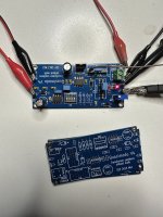
I've just get some Quasimodo boards from JLCPCB, if someone need a PCB I can send for free. (Got ten, one is enough for me...🙂)
I've assembled one yesterday night and everything seems fine
@Mark Johnson thank you so much for all your effort and help to us diyers.
ps: I know, I know...I've U3 upside down 🙂
Attachments
Last edited:
- Home
- Amplifiers
- Power Supplies
- Simple, no-math transformer snubber using Quasimodo test-jig