
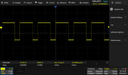
So Esmeralda does not yield a square wave, this owing to the symmetry of thresh-hold voltages etc.. Next go around will only use 4 of the inverters so that one can be used to "un-invert". We just need a big humped-back male who can ring the bell.
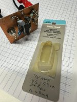
Depending upon which hex-inverter + Schmitt trigger you use the frequency will be a function of k/RC where k is peculiar to the device used. As W2AEW mentions, k is in a range of 1.2 to 1.9. In the particular case of the device described the constant was 1.9. As you can see, this was a Radio Shack "Harris Semiconductor"(1) device from the bin of non-discarded digital goodies. Anyone need a 6805?
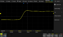
The 10%-90% rise time is ~ 4ns. I got pretty lucky with the ringing as I matched the length of the Rout resistors.
1) Harris, also known as Intersil, got their start making printing presses. Guess how IBM got into the punch-card business?
Depending upon which hex-inverter + Schmitt trigger you use the frequency will be a function of k/RC where k is peculiar to the device used. As W2AEW mentions, k is in a range of 1.2 to 1.9. In the particular case of the device described the constant was 1.9. As you can see, this was a Radio Shack "Harris Semiconductor"(1) device from the bin of non-discarded digital goodies. Anyone need a 6805?
The 10%-90% rise time is ~ 4ns. I got pretty lucky with the ringing as I matched the length of the Rout resistors.
1) Harris, also known as Intersil, got their start making printing presses. Guess how IBM got into the punch-card business?
Attachments
Very nice!
I gently suggest you might find it illuminating to look at the Quasimodo Results (ONLY) thread, especially posts #8 and #154. You may succeed in devising a diabolical procedure to tease out the oscillatory ringing frequency from the tabulated data in those posts. It's not what Sherlock Holmes calls "quite a three pipe problem", it's easier than that.
For example, I think the Hammond 185F230 transformer mentioned in post #154, when connected to the Quasimodo component values in that experiment, probably rang at 8.4 kilohertz. If we want our oscilloscope to display at least six periods of lumpity-bumpity ringing, that's a horizontal width of 710 microseconds. So the stimulus waveform should have a high time > 710us and a low time > 710us to display six full oscillation periods. The stimulus needs to be a frequency less than 0.7 kilohertz. If it has non-50% duty cycle, probably even slower.
The 6 kHz stimulus in post #2,722 is way too fast to optimize a snubber for this Hammond transformer. However, increasing the timing resistor in the Schmitt oscillator by a factor of ten, would drop the frequency by about a factor of ten, and that would be perfect.