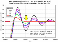
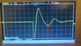
I'd recommend connecting the shield as per the end application - which typically means connecting the shield to the core/bell-end of the transformer.
Unfortunately the AS-3220 is a torroid. There are no endbells nor am I sure how to connect to the core.I'd recommend connecting the shield as per the end application - which typically means connecting the shield to the core/bell-end of the transformer.
Thanks. That was a configuration I did test before I pulled it off of the test bench. I didn't note any change in the value of Rs. I appreciate the info on best practice.
Scott
Scott
Based on that graph, 10R was soldered in. Thanks for the confirmation of what I was thinking was at least on the correct path.
It has been a VERY long time since I have delved into math like the snubber calcs. I probably could use the mental exercise if I had time, but graphically, isn't the ideal dampening occurring when the area under the trace for the negative peak approx. equals the area under the curve for the positive peak? (I am not factoring in the energy loss in Rs ).
It has been a VERY long time since I have delved into math like the snubber calcs. I probably could use the mental exercise if I had time, but graphically, isn't the ideal dampening occurring when the area under the trace for the negative peak approx. equals the area under the curve for the positive peak? (I am not factoring in the energy loss in Rs ).
Hello Gents,
I'm not a 100% sure in terms of what I am seeing on the scope and measuring. I've built the quasimodo jig, bought a scope and ran the tests. See results.
The transformer has actually 2 primaries which I both shorted but it also has 2 secondaries. I only shorted 1 half of the secondary and the other half is connected to the jig. This is pretty much my first scope experience so obviously not a 100% comfortable with what I'm actually doing.
My questions are:
Do I need to short the not used secondary winding as well? I probably do I just forgot it🙂
I've used the "standard" values for the capacitors > 10nF and 150nF. To flatten the ringing the trimpot ended up with value of only 19 ohms. I've attached the scope measurements but as mentioned..not 100% confident what I'm looking at.
Looking for some experienced advise obviously🙂
thx in advance
Willem


Trimpot removed.....


Trimpot measuring 19 Ohms
I'm not a 100% sure in terms of what I am seeing on the scope and measuring. I've built the quasimodo jig, bought a scope and ran the tests. See results.
The transformer has actually 2 primaries which I both shorted but it also has 2 secondaries. I only shorted 1 half of the secondary and the other half is connected to the jig. This is pretty much my first scope experience so obviously not a 100% comfortable with what I'm actually doing.
My questions are:
Do I need to short the not used secondary winding as well? I probably do I just forgot it🙂
I've used the "standard" values for the capacitors > 10nF and 150nF. To flatten the ringing the trimpot ended up with value of only 19 ohms. I've attached the scope measurements but as mentioned..not 100% confident what I'm looking at.
Looking for some experienced advise obviously🙂
thx in advance
Willem
Trimpot removed.....
Trimpot measuring 19 Ohms
Hello Willem,
ALL windings except the one under test HAVE to be shorted! All "other" secondaries and ALL primaries!
Your snapshot 2 shows severe overdamping! You need higher Rs! Post #1807 show a red trace which you need to meet for your transformer: One (1!) overshoot, "dying down" to the "0-Line" without an understoot - then you're there. This, from my experience, can be achieved in less than a minute with ANY transformer secondary winding. After alinging many transformers, I am using a 100Ohm Trimmer (Rs>100Ohms is very rare when using Cs 100nF in my experience) from the start, so the (quationable) low resistance part of a 1.5kOhms trimmer is avoided. Just try it 😉
Good luck!
Winfried
thx Winfried... will give it another go. Was thinking about a lower range trimpot as well but dont have one yet🙂... will run a couple of tests and post them here with the other secondary shorted as well.....
w.
w.
Hello Rick,.....i've pretty much read everything there is to read🙂...I'm just a first-timer with the scope but I'm getting there I think.🙂
Update: I shorted the secondary winding which is not measured. The trimpot is now at 18 Ohm and I can't seem to get it much better then this. I thinking it has something to do with that second secondary winding...not sure though.....


when I measured the other half of the same secondary I get a more expected result after some adjustments with a trimpot value of 22 Ohms.

Hola Sr. Mark Johnson.
Ante todo disculparme por mi falta de conocimiento.
Esta versión de Cheapomodo Rev3 la he hecho en la protoboard, con la variante de usar el transistor BC546 en lugar del 2N3906 y TLC555ip, en lugar del SE555.
El problema que tengo es que no logro visualizar las formas de ondas con el osciloscopio, para poder hacer las correcciones correspondientes, el ajuste del osciloscopio es en 1 voltio y el tiempo en 2000us, y no veo nada, como si tuviera la sonda desconectada.
Me podrian ayudar como tengo que configurar el osciloscopio para ver las senales?
Gracias de antemano.
Saludos
Juan
Hello Mr. Mark Johnson.
I'm sorry I put the query in Spanish without realizing it.
First of all, I apologize for my lack of knowledge.
I made this version of Cheapomodo Rev3 on the breadboard, with the variant of using the BC546 transistor instead of the 2N3906 and TLC555ip, instead of the SE555.
The problem I have is that I can't visualize the waveforms with the oscilloscope, to be able to make the corresponding corrections, the oscilloscope setting is 1 volt and the time is 2000us, and I don't see anything, as if the probe was disconnected.
Could you help me how do I configure the oscilloscope to see the signals?
Thanks in advance.
Greetings
Juan
Try 1 usec/div timebase and 1 V/Div amplitude
About 1/2 down this link I have a section on building and using a quasimoto.
About 1/2 down this link I have a section on building and using a quasimoto.
- Home
- Amplifiers
- Power Supplies
- Simple, no-math transformer snubber using Quasimodo test-jig

