PCB CAD files for manufacturing boards, are attached to post #1 of this thread. You can send them off to a PCB fab and they will ship boards straight to your home. Get a price quotation from the wonderful website www.pcbshopper.com . The Thru Hole PCB is 46mm X 97mm , 2 sided.
Hi guys,
I built the Quasimodo and everything works perfectly.
But I have one question:
If I switch e.g. 100nF across each rectifier diode, how big is CX on the Quasimodo board?
Since I don't have these diodes in the measurement, they have to be included in the CX.
Are these diodes still useful over the rectifier diodes?
If so, what value? So far I have always used 100nF.
Thanks for the help!
Best regards, Mike
I built the Quasimodo and everything works perfectly.
But I have one question:
If I switch e.g. 100nF across each rectifier diode, how big is CX on the Quasimodo board?
Since I don't have these diodes in the measurement, they have to be included in the CX.
- 410nF (4x100nF + 10nF snubber)?
- 110nF (1x100nF + 10nF snubber)?
- 400nF (without extra Subber-C)?
- 100nF (without extra Subber-C)?
Are these diodes still useful over the rectifier diodes?
If so, what value? So far I have always used 100nF.
Thanks for the help!
Best regards, Mike
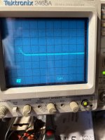
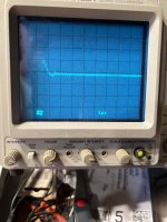
Getting back to using this on a 6 secondary Toroidy Audio Supreme power transformer. Took awhile to get back to using an analog scope, and can't quite get the trigger held off as much as I would like. The first shot is with 100R and the second shot is 12.5R. I think (?) this is in the ballpark (10 ohms or so). This is one of the 24V windings, primary shorted as 120V (parallel). I'll try it with the primary configured for 240V and see if it makes much difference.
And as a reply to Mikey70, above, I don't think there is any value to the old 100nf across each rectifier diode method. I could be wrong however.
And as a reply to Mikey70, above, I don't think there is any value to the old 100nf across each rectifier diode method. I could be wrong however.
Attachments


Perhaps. I raised it to 20 ohms. Changing to 240V primary configuration didn't change much. All of this is using the std. C configuration (10nf / 150nf). I'll go with that. The 8V windings were more or less the same, slightly higher, so I'll go with 27.4 ohms for those.
Just seen this. I have some spare as well, happy to send FOC, but I'm in Oz, so it would also be 2-4 week delay. PM me if interested.All, are there any Quasimodo V4 boards available for sale? Would like to purchase one.
Please let me know.
Thanks
Scott
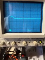
Back to running a few more tests. The first set of 3 pics is an 8V secondary, using 12R, 15R and 20R. The 2nd set of 3 is one of the 24V secondaries at the same resistances.
I think I will use 15R for the 8V secondaries, and 20R for the 24V secondaries.
I think I will use 15R for the 8V secondaries, and 20R for the 24V secondaries.
Attachments
-
 8V 12R Oct 01, 5 18 24 PM reduced.jpeg463.2 KB · Views: 130
 -
 8V 15R Oct 01, 5 19 33 PM reduced.jpeg398.9 KB · Views: 126
 -
 8V 20R Oct 01, 5 20 42 PM reduced.jpeg477.4 KB · Views: 128
 -
 24V 12R Oct 01, 5 23 25 PM reduced.jpeg473.9 KB · Views: 129
 -
 24V 15R Oct 01, 5 24 37 PM reduced.jpeg499.4 KB · Views: 128
 -
 24V 20R Oct 01, 5 25 47 PM reduced.jpeg513.4 KB · Views: 137
Rolotube kindly sent me two of his spare pcbs, which I have now populated. If a keen aussie needs a working board then pm me and I can pass one on.
Hello everyone,
for those who are interested:
I have an answer to my question in post #2442,
If you use a snubber ala Quasimodo, you no longer need capacitors across the rectifiers.
Either snubbers or capacitors.
Greetings Mike
for those who are interested:
I have an answer to my question in post #2442,
If you use a snubber ala Quasimodo, you no longer need capacitors across the rectifiers.
Either snubbers or capacitors.
Greetings Mike

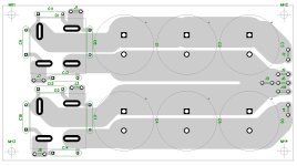
I have a question please, how is snubbing affected by the practice of putting "snubbing" capacitors across the diodes of the bridge rectifier?
In the PCB below the conventional arrangement, found in any number of power amps I have looked in, of a capacitor across each diode of the bridge.
For the purposes of adding a proper snubber, do I remove these and proceed as per figure 13 on Mark Johnson's paper in the OP or do one add a snubber on top of those caps?
If the latter, does the value of those individual diode caps add to the Crectifier for the purposes of sizing the other caps?
Attachments
I have a question please, how is snubbing affected by the practice of putting "snubbing" capacitors across the diodes of the bridge rectifier?
My personal preference would be to leave them out. Or if they are present, to remove them. If you decide to include and not remove those four capacitors, notice that each capacitor is in parallel with a rectifier. So you can calculate Crectifier_effective = (Crectifier + C_parallel) and then apply the Quasimodo design note, page 7, paragraph 3.
Thank you Mark, I thought that was case and hence can see why you would recommend removing the rectifier capacitors entirely.
The snubber must presumably be as physically close to the rectifier as possible?
The snubber must presumably be as physically close to the rectifier as possible?
I answered that years ago. It will take a while to find the post number. Meanwhile, ponder the question: "Why does the title of this thread say transformer snubber instead of rectifier snubber?"
So, another Quasimodo has seen the light of day. Tested with a 150 uH inductor the measured oscillation frequency was about spot-on with the predicted frequency: 130.4 kHz. The measured resistance to dampen it was somewhat higher than predicted: 78R in stead of 61R. But some wiggle room in what exactly is the right Zeta=1 waveform, so I trust mine is working as it should.
Attachments

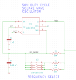
The next thing I wanted to test was if it matters whether the output signal is set for 50Hz mains frequency or 60Hz. From previous discussions about this topic I thought I already knew the answer (no, it doesn't matter) but I thought it was fun to test it anyway. So I started with the default R3= 39k and measured a transformer and dialed in a Zeta=1 waveform. Then I changed R3 for 47k5 (50Hz), 8k25 (about 5x) and 2k (about 25x) resistors and observed the waveform with the same Rs still in place. And it stayed exactly the same. So, the frequency of striking the bell does not influence the outcome for the snubber resistor needed to dampen the transformer ringing. I then chose R3, 4 and 5 values for 50Hz mains frequency and soldered them in. But I could have gone for the stock values just as well.
Unfortunately no pictures of this experiment as it turns out my scope only saves 1 channel with the option I used, and that turned out to be the extremely uninteresting square wave signal in this case 🙁
Unfortunately no pictures of this experiment as it turns out my scope only saves 1 channel with the option I used, and that turned out to be the extremely uninteresting square wave signal in this case 🙁
Quasimodo gives the same answer whether the bell ringing repetition rate is 17 times per second, 50 times per second, 60 times per second, 87 times per second, or 1138 times per second. You can verify this yourself by trying all four of the different frequencies which the DIPswitch on V4 Quasimodo selects.
(assuming perfectly accurate resistors and capacitors, the V4 DIPswitch offers: 122 Hz , 598 Hz , 2500 Hz , 2980 Hz)
This 24-to-1 frequency range allows DIYers to use old, analog, CRT scopes with Quasimodo and still get a reasonable (electron beam-on versus beam-off) duty cycle, so the trace is visible on the CRT face without needing to extinguish the room lights.
Changing resistors and/or capacitors to achieve exactly 50 Hertz for the bell ringing repetition rate, certainly does no harm. It also offers no benefit.
_
Attachments
- Home
- Amplifiers
- Power Supplies
- Simple, no-math transformer snubber using Quasimodo test-jig