Yes, that makes sense. Just a case of "it feels better" but I know (/ have seen) it makes no difference.
But first I should thank you for the effort in designing the Quasimodo and remaining active for 10 years now in this thread.
I will now use it to calculate snubbers for the PSU's of my Bugle and Pearl 2 phono stages.
But first I should thank you for the effort in designing the Quasimodo and remaining active for 10 years now in this thread.
I will now use it to calculate snubbers for the PSU's of my Bugle and Pearl 2 phono stages.
Last edited:
Schematics are not quite legible.A power transformer snubber is a wonderful thing for reducing or eliminating RFI from rectifier-induced LCR ringing. Unfortunately it's a huge pain to design and optimize a snubber. First you have to measure the transformer's leakage inductance and secondary capacitance, at about 100 kHz, which is not especially easy. Then you have to estimate the capacitance of your rectifier(s), which does not always appear on datasheets. Finally you plug these numbers into a formula that spits out snubber values -- and then you hope it's all correct.
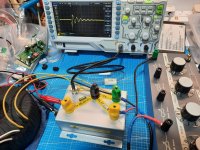
Shown here is a little test jig called "Quasimodo the bell-ringer" which makes this process a great deal simpler. Quasimodo connects an actual snubber across the transformer, smacks the transformer to make it ring, and you observe the ringing on an oscilloscope. Then you adjust a (25 turn) potentiometer on the jig, watching the scope to find the setting which completely damps out all ringing. And you're done! Just use the same snubber values in the end product, as you used on the test-jig, and success is yours. (The 25 turn trimpot is socketed for ease of measuring the final resistance that gave perfect damping).
Attached are some scope waveforms showing a Quasimodo jig driving an Avel Lindberg toroidal transformer (from the Akitika GT-101 power amp). I set the trimpot to 5 different resistance values, and got the 5 traces shown. When the trimpot was removed from its socket (R = infinity), I got the black trace. A setting of Rtrimpot = 109 ohms (red trace) gave "critical damping" with no ringing: see yellow arrowhead.
Quasimodo gave an optimum snubber having critical damping (Greek letter zeta = 1.0), without requiring any calculations and without measuring the transformer's inductance or capacitance. It is a quick procedure, too: set Rtrim to max, observe waveshape on scope while reducing Rtrim, stop when all ringing is completely damped out, remove Rtrim from socket and measure it with an ohmmeter. About 3 minutes from start to finish.
This Avel Lindberg transformer has dual primaries for 115V/230V operation. So I configured the primaries the other way and ran Quasimodo again: figure attached. Not surprisingly, the optimum snubber for 230V operation is (slightly) different than the optimum for 115V operation: 120 ohms versus 109 ohms. Plus or minus the error tolerance of my ohmmeter, of course!
I've also attached a .pdf note that contains more details, schematics, construction tips, user guide, more "Quasimodo in action" scope photos, plus a bit of theory and a list of references.
EDIT 1: I had a small number of extra PCBoards + kits of all parts, which I sold at my cost, in October - December, 2013. They are all gone now, and I have no plans to sell any more. I encourage any energetic and enthusiastic diyAudio member to organize a Group Buy, using the PCB Gerber files and Bills Of Materials I provide in this thread. "CheapoModo" (a low cost version of Quasimodo) kits and PCBs are available in the Vendor's Bazaar, here.
EDIT 2: I have attached the PCB Gerber files and the Bill Of Materials, for both boards (V3_SMD, and V4_thru_hole) right here, to post #1. So now they are very easy to find!
EDIT 3: (April 2022) I just stumbled across this "Yes Math!" application note from Texas Instruments, which calculates RC snubbers to eliminate ringing from switch mode power supplies: (link)
EDIT 4: Answers to frequently asked questions:
. .
- Build guide for V3 (SMD) is found in post #27
- Build guide for V4 (thru hole) is found in post #103
- 2 hour build time, quick-and-dirty Quasimodo on solderless protoboard (no PCB!) is found in post #18 and in (the CheapoModo thread)
- Substitute parts recommendations are found in the Bill Of Materials
- How to choose a MOSFET besides the ones in the BOM, is found in post #175
- How to check your own BOM before purchasing components, is found in post #203
- diyAudio members who have ordered their own sets of PCBoards from a PCB fab, using the Gerbers provided here, include: gazzagazza, luvdunhill, Borges, stormsonic, cwtim01, normundss, dsolodov, EUVL, kissmurphy, stephengrenfell, Piersma, SyncTronX, yoaudio, andrensairr. You can PM them to find out how easy or difficult it was.
Why did you quote all of that?
All the lettering in the .png files attached is legible using 3 different photo viewers on my PC with my browser and monitor.
Did you try enlarging them? Did you try downloading them locally and viewing them with another piece of software?
All the lettering in the .png files attached is legible using 3 different photo viewers on my PC with my browser and monitor.
Did you try enlarging them? Did you try downloading them locally and viewing them with another piece of software?

Today I measured another transformer (Block RTE40 230V, 2x15V 40VA). Question to the experts: which of the following 2 inmages looks more like a Zeta=1 damped waveform? The first one is with Rs = 33R5, the second one with Rs = 15R4. Unfortunately the vertical scale is different (should mind that the next time), first one is 5V/div, second one 2V/div.
33R5

15R4

33R5 has just a tiny dip/hump left (30R will probably make that go away). Second one takes some time to settle down and looks more irregular.
33R5
15R4
33R5 has just a tiny dip/hump left (30R will probably make that go away). Second one takes some time to settle down and looks more irregular.
Thank you @Mark Johnson for Quasimodo and in particular for Quasimodo_jig_revA.pdf - a very illuminating document. It seems I have overlooked transformer ringing, my attention drawn to more exciting stuff downstream.
I got here via the Pearl3 thread, which i am excited to build but will now likely put on hold while I Quasimodo everything in the house. ;-)
Best,
Tony Z
I got here via the Pearl3 thread, which i am excited to build but will now likely put on hold while I Quasimodo everything in the house. ;-)
Best,
Tony Z
I got here via the Pearl3 thread, which i am excited to build but will now likely put on hold while I Quasimodo everything in the house. ;
Thanks for the chuckles, and don't forget the next door neighbours ARC welder.
Cheer!
Rob
I should have said "...Quasimodo all my AV gear...".
I emailed my neighbour a link to this thread. He can build his own Quasi for his arc welder. I won't lend him mine - I suspect his Quasimodo might need a heftier Mosfet to drive the output.
I emailed my neighbour a link to this thread. He can build his own Quasi for his arc welder. I won't lend him mine - I suspect his Quasimodo might need a heftier Mosfet to drive the output.
Today I measured another transformer (Block RTE40 230V, 2x15V 40VA). Question to the experts: which of the following 2 inmages looks more like a Zeta=1 damped waveform? The first one is with Rs = 33R5, the second one with Rs = 15R4. Unfortunately the vertical scale is different (should mind that the next time), first one is 5V/div, second one 2V/div.
33R5
View attachment 1239970
15R4
View attachment 1239971
33R5 has just a tiny dip/hump left (30R will probably make that go away). Second one takes some time to settle down and looks more irregular.
Anyway, you can redo your testing with both scales set the same for easier examination?
Glad I built 2 of these - my first one decided to produce strange signals resulting in gibberish. Second one to the rescue!
Search thread titles for Cheapomodo ; it's a reduced parts count version that goes together in an hour on a piece of veroboard / stripboard . Very inexpensive backup unit, and/or a loaner for audio buddies too lazy to build a Quasimodo of their own.
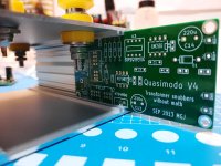
Finally completed this “Quasimodo”. Though there were some problems during the building stage but were solved and now in service condition.
I would like to say thank you to Mark Johnson for the contribution so that I can have this tool for my on-going DIY projects.
I would like to say thank you to Mark Johnson for the contribution so that I can have this tool for my on-going DIY projects.
Attachments

I see that some folks have ordered from JLC pcb, how did you manage it as i cannot get there system to recognise the gerber files?
I tried this just now (for TH):
1) Download the quasimodo TH gerber and everything zip file from Mark's first post in this thread.
2) Unzip this file and look for the "qmodo_TH_Gerbers_for_seeed.zip" file. jlcpcb accepted this file without issue.
Hope this helps.
1) Download the quasimodo TH gerber and everything zip file from Mark's first post in this thread.
2) Unzip this file and look for the "qmodo_TH_Gerbers_for_seeed.zip" file. jlcpcb accepted this file without issue.
Hope this helps.
I did exactly the same as @Dennis Hui writes. 'Did that just a few weeks ago, all went as expected and the boards look good.
This was my first ever JLCPCB order, and everything went as @MJ wrote in his thread:
Thanks to @Mark Johnson !
This was my first ever JLCPCB order, and everything went as @MJ wrote in his thread:
Ordering PCBs online (using Gerber files): A walkthrough. --- featuring the fab "JLCPCB"
Might be worth a read.Thanks to @Mark Johnson !
- Home
- Amplifiers
- Power Supplies
- Simple, no-math transformer snubber using Quasimodo test-jig