
Still got a couple TH PCBs left for EU shipping, anyone interested, please drop me a message.
Sharing here my Mouser BOM with all available parts. ProjectID: 1bf679e00a
Instead of ICM7555IPAZ, the TLC555CPE4 can be used as well; both are available currently.
Instead of ICM7555IPAZ, the TLC555CPE4 can be used as well; both are available currently.
Hi folks,
today I was told by a technician in another hifi forum that transformer snubbing would be / is obsolete with the use of "silicon-carbide technology diodes". I find this hard to believe and would like to verify this, so sharing of any experience would be much appreciated!
Thanks and Regards,
Winfried
I measured transformer ringing with a bunch of different diodes plugged in to the exact same test fixture, so any differences in the measured ringing were due to differences in the diodes alone. I published my results in a Linear Audio magazine article, it is here . The first three lines of that article say:
Quote:
One of the units tested was in fact a Silicon Carbide diode made by Cree research; datasheet attached below. It rang -- they all rang -- so at least that one particular example of Silicon Carbide rectifiers + transformer , was less than perfect. However, the final sentence of the Abstract offered some encouraging information:
Quote:
They all rang without snubbers, and they all failed to ring with a 1R+2C snubber. Without=ick, with=yum .
Quote:
ABSTRACT: Power transformer secondary ringing was measured with 48 different semiconductor diodes; ringing amplitude was 10-20X lower with the best diodes than with the worst. They all rang, including Schottkys and HEXFREDs [and Silicon Carbide --mj] ... (continued below)
One of the units tested was in fact a Silicon Carbide diode made by Cree research; datasheet attached below. It rang -- they all rang -- so at least that one particular example of Silicon Carbide rectifiers + transformer , was less than perfect. However, the final sentence of the Abstract offered some encouraging information:
Quote:
... (continued from above)... A 1R + 2C snubber directly across the secondary completely eliminated ringing in every case.
They all rang without snubbers, and they all failed to ring with a 1R+2C snubber. Without=ick, with=yum .
Attachments
Winfried, to add to Mark's response, power transformers are not typically selected based on their secondary winding leakage inductance. In addition, some people deploy filters with very large capacitance directly after the rectifier, and the power transformer impedances may be such as to cause exceedingly peaky current pulses with similarly abrupt current change to zero when a diode turns off. So imho it is not appropriate to generalise that there would be no rectification related noise eeking in to any particular audio circuit just due to the selection of diode.
Some types of power supply inherently don't typically generate such transient noise - especially audio amps with valve diodes, and similarly valve amps with high voltage B+ supplies (due to the relatively high shunt capacitance and DCR of the secondary windings). I was just able to measure some ss diode (1N4007) rectification induced noise on the secondary HT winding voltage in a valve amp power supply, but it was very low (<-90dB) relative to the HT winding, and I couldn't discern any such noise signature on the filtered DC B+.
Some types of power supply inherently don't typically generate such transient noise - especially audio amps with valve diodes, and similarly valve amps with high voltage B+ supplies (due to the relatively high shunt capacitance and DCR of the secondary windings). I was just able to measure some ss diode (1N4007) rectification induced noise on the secondary HT winding voltage in a valve amp power supply, but it was very low (<-90dB) relative to the HT winding, and I couldn't discern any such noise signature on the filtered DC B+.
Thanks for confirming my suspicions! SiCarbide diodes seem to address a different (sound relevant) issue than the snubber does. Here's a picture supposedly describing the SiCarbide diode advantage:
https://up.picr.de/44138232fc.png
So far as I can interpret it, this shows current spikes (vertical axis) generated by a rectification diode switching (left diagram) which does not appear with a SiCarbide diode (right diagram). To me this is a different issue than the ringing caused by the switching edge itself or may just make the bell striking stronger (?). The claim is that the right diodes make sound cleaner, making a snubber obsolete which I doubt and you seem to confirm.
I don't want to drag this out too far as it's potentially drifting off-topic, but maybe you folks can just give your interpretation of the diagrams, so I can put this to rest with a valid statement.
Thanks,
Winfried
No, the issue is related. Hard-switched switchmode power supplies can operate diodes in a very aggressive manner, and so diode datasheets show that by way of a reverse recovery test setup that applies a known constant forward current, and a known dI/dt ramp down to 0A, and most diodes exhibit a reverse recovery effect that is a big issue for switchmode supplies. But a normal audio equipment related power supply operates the diode quite differently, so the diode datasheet plot you are looking at can be very enticing to use for selection, but also very deceiving to use for selection, as the application conditions are very different.
PS. your plot wasn't from a datasheet, sorry, but if you look around you are likely to find technical papers or datasheets of diodes that graphically show reverse-recovery performance.
PS. your plot wasn't from a datasheet, sorry, but if you look around you are likely to find technical papers or datasheets of diodes that graphically show reverse-recovery performance.
Last edited:
Winfried, note that although the C3D04060F CREE diode used by Mark is 4A rated, a significant disadvantage of SiC diodes is the relatively low repetitive peak continuous current rating of circa 11A. So effectively that 4A SiC diode has about half the current rating of a 1N4007 (which can cope with a repetitive peak of about 20A). Mark's test circuit may have even reached that peak limit (not enough detail in the paper to identify the transformer impedance).
Having just aquired a V4 board I'm searching for a parts list relevant to UK suppliers. Anyone have one please?
Check out the BOM here in this post.Having just aquired a V4 board I'm searching for a parts list relevant to UK suppliers. Anyone have one please?
Thanks - I did look at a number of pages but unfortunately not this one!Check out the BOM here in this post.
Just checked that shipping to the US is possible as well and for the same price! Not bad at all and takes around 4 working days to deliver.Still got a couple TH PCBs left for EU shipping, anyone interested, please drop me a message.
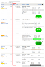
Ten minutes ago, I got price quotes from www.pcbshopper.com for a purchase of ten (10) Quaisomdo V4 thru hole boards, to be shipped to USA. Quoted prices ranged from ($11.36 , delivery in 16 days (blue rectangle)) to ($29.63 , delivery in 5 days (black rectangle)). That's a cost of $1.14 to $2.96 per board, delivered to you.
The Gerber files needed by the PCB fab, are attached to post #1 of this thread. Use the "seeed" version for all fabs in the world EXCEPT OSHpark.
_
The Gerber files needed by the PCB fab, are attached to post #1 of this thread. Use the "seeed" version for all fabs in the world EXCEPT OSHpark.
_
Attachments
I need help from mark johnson
I modified a power supply like the crown 1c-150 shown in marks instructions with a bridge rectifier that had two .01uf ceramic caps from each side of the secondary of the transformer to the signal ground of the power supply. This was not a center tapped transformer so I don't know why the manufacturer used 2 caps instead of just one across the secondary.
Thus I think since both caps have a common ground the net effect of the capacitor in series is half the capacitance of each capacitor or .05uf cap across the secondary
So when I used the Quasimodo I did not remove the existing caps and used a .01 uf polypropylene cap directly across the secondary and like a 40 ohm resistor in series with a .15 uf cap and achieved critical snubbing
Should I remove the existing .01uf ceramic caps now?
I think I should have removed them and then snubbed
Is there any harm in leaving them in?
The new polypropylene cap should swamp out the existing ceramics because it is twice the value
I would assume that if i achieved critical damping with the ceramics in the circuit there is no harm in leaving them in
You'll have better chances of success if you address requests to ALL members subscribed to this thread, instead of to one person. Two hundred fifty thousand heads are better than one.
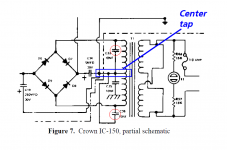
You'll also have MUCH better chances of success if you include schematic diagrams or photographs or both, of equipment that you want help with. For example, here is the Crown IC-150 schematic taken from page 6 of the Quasimodo design note. You can see that it does have a center tapped transformer. So it's difficult to understand why you mention a not-center-tapped transformer, unless you include a circuit schematic with all components clearly labeled.
_
Attachments
thanks Mark.
My questions goes to all the heads out there.
the power supply in question was to a pioneer P3A turntable power supply.
There is no schematic available to my knowledge.
The transformer is extremely simple.
A single winding primary and a single winding secondary.
I mentioned the Crown ic150 schematic mark provided only because it was the most similar but instead of a single winding transformer, the crown had a center tapped secondary, which is why there are two caps to ground.
In this circuit there is a .o1uf ceramic cap from each secondary of the transformer to the ground of the first resevoir cap after the rectifier bridge.
Should I remove them if I critically snubbed the transformer with a new cap of .o1uf across the secondary of the transformer, one another one with a 40 ohm resistor in series with a .15uf across the secondary..
I cant figure out why the caps are in there in the first place.
I listened to voices on a simple recording with the transformer snubbed and not snubbed
The voices became clearer and less tizzy with the snubber but there was some loss of air or blunting effect with a low esr .01uf Teflon cap across the transformer secondary of a tube amp preamplifier. A cat pre amp .
Ken Stevens does critically snub his rectifiers and believes they help sonically
He uses uf rectifiers and then snubs them
I use a 285 amp low voltage drop vishay hexfred diode module critically snubbed using my Quasimodo
The 285 amp diode module had very low voltage drop for a hexfred and was audibly superior
They are $30 each
All my friends bought them and heard the difference
Low voltage drop hexfreds always correlated with better sound cleaner bass
Vishay has new 5th generation hexfred diodes optimized for either hyper speed or lower voltage drop
The 75 amp single diode optimized for low voltage drop were superior but no match for the 280 amp vishay diode module
I use only a 150 amp diode module in my tube preamp critically snubbed using the Quasimoto
The 280 amp diode module is in the turntable power supply where it is even more audible
A far nastier signal present within the amplifier enclosure is the charging current flowing through the rectifier diodes into the reservoir capacitors. Recall that the rectifier diodes only conduct when the secondary voltage of the transformer exceeds the voltage on the reservoir caps. Thus, the diodes only conduct for a small fraction of the mains cycle. As the charge drained by the load will need to be replenished while the diodes conduct, the charging current can be significant, and often reaches tens of ampere even in a modest power amp. Furthermore, the charging current is a pulse train, which further increases the potential for electromagnetic coupling.
A small air core inductor between the bridge and the first cap produced more audible benefit here than the snubber
One engineer came to the following conclusion because he saw no effect of the snubber on the audio amplifier distortion
I say I heard it so I disbelieve his statements:
“It should be noted, however, that the addition of snubbers makes no difference in the output of the power supply or in the output of the connected audio amplifier. Thus, any claims of audiophile superiority resulting from the addition of snubbers should be viewed with skepticism. This is especially true in the cases where the proponents of snubbers also sell you the tools for their implementation. As always: Extraordinary claims should be backed up by extraordinary evidence.
Rather than adding snubbers, I suggest following the current best practices regarding chassis layout and wiring. Particularly, I suggest routing the input wiring for the amplifier as far away from the power transformer as practically possible.”
Good advice despite his wrong general conclusion
- Home
- Amplifiers
- Power Supplies
- Simple, no-math transformer snubber using Quasimodo test-jig