Thanks everybody, I arranged with xaled. There are quite few options if one is really interested, Davide (Nikon1975) still has the SMD version.
Thanks everybody, I arranged with xaled. There are quite few options if one is really interested, Davide (Nikon1975) still has the SMD version.
Hi savvas,
I hope you get the correct boards you are looking for.
I PMed and emailed Denis pics of the incorrect boards yesterday, I'm waiting to hear back from xaled (Denis) as I was expecting the Quasimodo v4 through hole and received the
Cheapomodo v3. I've got parts for Quasimodo v4, but none for the Cheapomodo, well well possibly but then I'd have to jerry rig the board to fit the Quasimodo's larger parts which defeats the purpose... AND I don't think the area of the Cheapomodo, v3 will accommodate hacking in an 8-pin (4-switch) dip switch. Now if my life depended upon it, I probably would...but that's not the point.
I probably should have just taken the plunge and had a China fab make them.
Denis, what say you?
Cheers,
I'm not sure if I've got a problem with my Quasimodo SMD version. I've used a bit and didn't really notice until now that I consistently get a Rs value of about 6 to 8 Ohms on every transformer I just measured. A 10va, a 15va, a couple 50va and a 160va. I suppose they all could have this same result but it seems unlikely. It's a similar result I get if the transformer isn't connected to the Quasimodo. The trace does change when I connect the transformer but the nulling of the ringing is seeing the similar Rs value.
I follow Mark's guide when connecting the transformer and short the primary.
Anyone else getting these consistently low Rs values?
I follow Mark's guide when connecting the transformer and short the primary.
Anyone else getting these consistently low Rs values?
Your board might be faulty. You could test this hypothesis by connecting a fixed inductor to the screw terminals on your Quasimodo V3's terminal block. Chose an inductor whose inductance is greater than 100 microhenries. Or if you have none, just scramble-wind at least 200 turns of insulated wire on an iron nail to make your own "ghetto inductor". Then connect to QM and dial the potentiometer for zeta=1 damping. Is it ALSO 6 to 8 ohms? If so then your board definitely IS faulty.
In-situ Rs vs Quasimodo Rs
Hi Barca
Read you post of Nov 27, 2015. Very interesting.
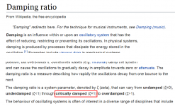
1. Don't you mean that in-situ Rs damps critically at half the resistance 330R compared to what Quasimodo gave 625R?
2. Is it true that this in-situ test used a RC snubber whereas Quasimodo used a CRC snubber, and thus the Rs would be different?
Denis
Adjusting now the trimmer resistance for the damping factor Zeta=1.0, I obtained the waveforms in the sixth figure; the trimmer resistance at this setting measured 330R, i.e. twice the value obtained with Quasimodo and the primary and one of the two secondaries shorted.
... with Quasimodo I measured Rs=625R for Zeta=0.707 in such a configuration
Hi Barca
Read you post of Nov 27, 2015. Very interesting.
1. Don't you mean that in-situ Rs damps critically at half the resistance 330R compared to what Quasimodo gave 625R?
2. Is it true that this in-situ test used a RC snubber whereas Quasimodo used a CRC snubber, and thus the Rs would be different?
Denis
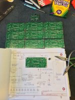
Cheapo2Quasi-ModoMagik
Just as the title says since I have the incorrect boards.
You heard me correctly I have the Cheapo-modo v3, through hole boards and I'm going to try and put some of the Quasimodo v4 parts in that one.
Part A
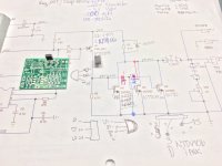
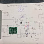
Step 1: Examine the schematics for each device then get the data sheets for the devices and see if I could correlate them and fit them on the board.
Step 2: Study them, over and over to make sure I knew the proper pinouts of the devices, their location, and where they were in the schematic, and their orientation on the board.
Step 3: Write down the DGS terminals on the schematic, use the board layout and original device orientation and device terminals SGD and GDS know where to place the terminals of the substiture devices in their corresponding locations on the board.
Step 4: Identify the NTD4906 GDS pins to place into the three different 2N7000 JFET pin's locations; that is, 3 sources, 3 gates, and 3 drains. Intuitively I thought I might get lucky and not have to twist and bend
the pins of the NTD4906 into a pretzel to get it to fit.
Step 5: Why did it take me so long? Well my bench is about 1/3 finished and it is a different enough configuraton that I need to work on stuff and put stuff together and take stuff apart so I won't end up screwed at a later time and not be able to remove shelves and replace them in a different location.
Part A has been laid out and it is on the PCB, not soldered yet.
Part B is to fit the DIP8 MPC1407 into the 3 pin EBC transistor slot. I think this can work as shown: Pins 1, 8 = Vcc Pin 2 = Input Pin 4, 5 = Ground
Pin 6,7 = Output
Not too sure complety....might blow something up trying to get it to work.
Part C is then to figure out where all the little caps are going as there is no provision for them in the chepomodo.
Part D also have to figure out how to power it and keep some
voltages separate from signals, etc.
Cheers,
Just as the title says since I have the incorrect boards.
You heard me correctly I have the Cheapo-modo v3, through hole boards and I'm going to try and put some of the Quasimodo v4 parts in that one.
Part A
Step 1: Examine the schematics for each device then get the data sheets for the devices and see if I could correlate them and fit them on the board.
Step 2: Study them, over and over to make sure I knew the proper pinouts of the devices, their location, and where they were in the schematic, and their orientation on the board.
Step 3: Write down the DGS terminals on the schematic, use the board layout and original device orientation and device terminals SGD and GDS know where to place the terminals of the substiture devices in their corresponding locations on the board.
Step 4: Identify the NTD4906 GDS pins to place into the three different 2N7000 JFET pin's locations; that is, 3 sources, 3 gates, and 3 drains. Intuitively I thought I might get lucky and not have to twist and bend
the pins of the NTD4906 into a pretzel to get it to fit.
Step 5: Why did it take me so long? Well my bench is about 1/3 finished and it is a different enough configuraton that I need to work on stuff and put stuff together and take stuff apart so I won't end up screwed at a later time and not be able to remove shelves and replace them in a different location.
Part A has been laid out and it is on the PCB, not soldered yet.
Part B is to fit the DIP8 MPC1407 into the 3 pin EBC transistor slot. I think this can work as shown: Pins 1, 8 = Vcc Pin 2 = Input Pin 4, 5 = Ground
Pin 6,7 = Output
Not too sure complety....might blow something up trying to get it to work.
Part C is then to figure out where all the little caps are going as there is no provision for them in the chepomodo.
Part D also have to figure out how to power it and keep some
voltages separate from signals, etc.
Cheers,
Attachments
Down near the bottom of post #1 it says
Look at all those brave people! They overcame their fears. They managed to order PCBoards from overseas, using the Internet. And they succeeded! They actually got the PCBs they wanted. Bravo.
... diyAudio members who have ordered their own sets of PCBoards from [PCB fab houses] using the Gerbers provided here [attached to post #1], include: gazzagazza, luvdunhill, Borges, stormsonic, cwtim01, normundss, dsolodov, EUVL, kissmurphy, stephengrenfell, Piersma. You can PM them to find out how easy or difficult it was.
Look at all those brave people! They overcame their fears. They managed to order PCBoards from overseas, using the Internet. And they succeeded! They actually got the PCBs they wanted. Bravo.
Hi Mark,
I've been wading through various forums for most and mourning now as I can't find the comparative site for various board makers. Shame on me. Perhaps you or someone can post the link again here.
cheers,
I've been wading through various forums for most and mourning now as I can't find the comparative site for various board makers. Shame on me. Perhaps you or someone can post the link again here.
cheers,
Thanks Dennis.
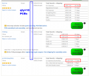
Yes, I just got through submitting it, not sure it went according to plan as their system didn't see any of the gerber files, but it saw the 1OSHpark TH Gerbers.zip and took the zip file. When I first tryed to upload from the unzipped folder, it didn't recognize any of the files?
Generally painless as this was my first ever PCB order. This first page was the bear for me! What size was the board? Oh My! I think all the options were pre-selected including the 1 oz board. I couldn't make any changes that I know of to the boards. Sometime prior to now, I could view the files, but this time my computer wanted to search for the gerber applications on the internet...go figure.
Anything else selected almost doubled the price including solder mask color etc. selecting 2 oz board definitely doubled the price & shipping went up also.
Not sure how the rest of this plays out, I'll wait and see. In the mean time.
Cheers,
Post Script - I think I'm going to hold off on the trying to implement QuasiModo v4 on the Cheapo-V3 board. Save parts, time and frustration.
Last edited:
Please go back and read through the most recent 25 posts. The name you're looking for was posted on JFK Day 2018, less than 25 posts ago. If you can't remember JFK Day just read all 25 posts. It will take less than 25 minutes.
Finally the Quasimodo TH V4 boards have arrived
Ta da,
I'm happy, I did it, even with the threat of Tariff and other BS, I over came my uncertainty and bought the boards from China and got them delivered in less than a week.
Dennis, I had good luck too.
Mark, thanks for making this available for Everyman.
Cheers,
Post Script - (Tiffany's seal of approval)
I can now remove my palms from pressing into my cranium.
Ta da,
I'm happy, I did it, even with the threat of Tariff and other BS, I over came my uncertainty and bought the boards from China and got them delivered in less than a week.
Dennis, I had good luck too.
Mark, thanks for making this available for Everyman.
Cheers,
Post Script -
(Tiffany's seal of approval) I can now remove my palms from pressing into my cranium.
Attachments
Does anyone have boards or kits available?
SyncTronx I would be interested if your planning to sell off extra boards and parts. Which boards are you producing?
SyncTronx I would be interested if your planning to sell off extra boards and parts. Which boards are you producing?
I'm still waiting for mine.got them delivered in less than a week.
Boards w/ Devices
Hi Fritz,
I sent you a pm. I've can sell a board with the three devices. it was a little bit more for expidited shipping etc and I don't have enough of anything else to make kits for this.
Heck, I've got to fool around with my own resistors and caps to have a full board for myself. It is what it is.
Cheers,
Everyone who hopes to call themselves a DIYaudio builder, should have at least one successful Chinese PCB order under their belt. The good news is: this is not unimaginably difficult. The better news is: you will feel such a sense of pride and of Major Accomplishment, thinking about your own bravery and your own persistence when you succeed!
Look at the names in post #1411. It's a great big old, LONG list. Add to that list, dennismiller55 and SyncTronX and (I predict) yoaudio. Every one of those people DID IT! If they did it then, by God, You Can Too!! Overcome your fears. Follow Morpheus's advice in the Matrix movies, and Free Your Mind. You are an awesome and powerful builder. Build!!
When you order 10 PCBs but only use one or two of them, sell the rest or give them away or help your fellow diyAudio members in whatever way feels most comfortable to you. Heaven knows there are a lot of timid and frightened people -- do what you can to reassure and comfort them! Help them become as brave as you.
A "Black Belt in Chinese PCB Ordering" is still a Black Belt. Work towards it, earn it, take great pride in your success! You can do this.
- Home
- Amplifiers
- Power Supplies
- Simple, no-math transformer snubber using Quasimodo test-jig