Well put, MJ. I received tremendous satisfaction from my first ever PCB order and subsequent build, although it was a different project. Part of the diy journey. Empowering. You will, I promise, marvel at the efficiency and the smallness of the world. Go for it!
BK
BK
Benefits of snubbing the transformer feeding a valve (tube) rectifier
I built a small power supply using the 6BY5GA damper diode. Treated nicely, this valve (tube) works well as a full-wave rectifier fed by the centre-tapped secondary of a mains power transformer. I have it delivering 330V and 75mA. "Treated nicely" means:
After filtering with capacitors and inductors, my ancient Tek scope showed residual ripple. Every 5mS there was a ringing spike, 2mV peak to peak, lasting about 1.5mS. The 5mS interval corresponds to 200Hz, the frequency I would expect from two diodes rectifying our 50Hz mains supply. I wish I could post photos but none of my snaps came out well - it was textbook ringing behaviour.
After applying my Cheapmodo, I arrived at snubber values and applied them to the secondary windings. Voila!!!! No more ringing. Ripple is now well down into the microvolt region, under -130dB relative to the 330V DC.
Very satisfying.
Thanks again, Mark, for this useful little test jig.
I built a small power supply using the 6BY5GA damper diode. Treated nicely, this valve (tube) works well as a full-wave rectifier fed by the centre-tapped secondary of a mains power transformer. I have it delivering 330V and 75mA. "Treated nicely" means:
- using negative temperature coefficient resistors on the primary to control inrush current; and
- including a 100 Ohm resistor in series between each secondary and each anode (to meet or exceed the input impedance indicated in the Tung Sol data sheet for the 6BY5G).
After filtering with capacitors and inductors, my ancient Tek scope showed residual ripple. Every 5mS there was a ringing spike, 2mV peak to peak, lasting about 1.5mS. The 5mS interval corresponds to 200Hz, the frequency I would expect from two diodes rectifying our 50Hz mains supply. I wish I could post photos but none of my snaps came out well - it was textbook ringing behaviour.
After applying my Cheapmodo, I arrived at snubber values and applied them to the secondary windings. Voila!!!! No more ringing. Ripple is now well down into the microvolt region, under -130dB relative to the 330V DC.
Very satisfying.
Thanks again, Mark, for this useful little test jig.
Congratulations on your success, Bondini! Glad to hear about a snubbing victory in valve equipment.
This is an interesting build. It's also an interesting challenge to use for the first time.
So much stuff to figure out...
Have a look see.
So much stuff to figure out...
Have a look see.
Attachments
Bondini,
I'm right behind you. I've got more then a few tube amp transformers to check upon. That octopus transformer (a.k.a. Octoformer) shall be interesting, Deluxe Reverb Amp. Then the big one, is electrical equivilent to the HiWatt 50. Finally the multi tapped secondary for different projects 8.6V to 52V no load, probably 5V to 48V with a load.
Of course I started with the big one, Multi tapped primary 120V, 230V,240V transformer with the dual center tapped secondaries, that is the B+ and one for the filaments. Mark's
"Field Guide for Modo's" was quite useful, I ended up using a combination of row 4 and row 5 from Figure 13.
The only real issue I had was language and orientation related when placing the scope probes, To the right of the C2 capacitor....is that when we are looking down at the completed board or is that looking at the schematic of Figure 4? Not so good if we place the scope probes at the same node.
However, there are provisions for the Scope & it's ground connection. I eventually figured it out after removing the hands from the cranium.
I'll follow up when I get the chance.
Cheers,
Last edited:
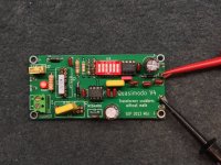
QuasiModo V4 Though Hole Initial Test Batch
Here is my first pass at testing a rather complex transformer. It is for the classis Hi Watt 50Watt amplifier. After reading through Mark's Simple, No-Math Transformer Snubber using "Quasimodo" Test Jig, RevA, 07 Sept 2013 (post#1 this thread) I found that Fig. 13 Rows 4 & 5 were an appropriate start, as follows:
Row 4 - Independent Secondaries
Row 5 - Center Tapped Secondary
I tied the primary black and red wires together which corresponds to 240 VAC.
I used the center tapped filament secondary tieing the blue and green wires together for one connection and used the black wire for the other.
After hooking everything up I noticed that I wasn't getting the square wave, rather it's a distorted square wave with significant curve. I'm guessing using film caps with their Low D, and ESR were the problem.
With the first test you can see both the rounded square wave and the ringing, which might be from it being over damped guessing.
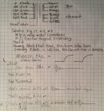
As I changed the capacitors of Cx and Cs as Mark explained Cs would have the most affect on the damping. This is shown in my own notes progressing from test 1 to test 6.
Test 1: Cs = .15uf, Cx = .1uf.
Test 6: Cs = .1uf, Cx = .01uf. Finally I adjust RV1 = 16 ohms
This gave me the what Mark has shown to best values to use based on the Scope's image.
I first have to fix the square wave and make it a square. Then I think I have to use the dip switches to get a brighter image on the scope. w/o that I have to really dial up the intensity.
Anyway this is pretty good stuff and should help me dial in Music Instrument amplifiers, Stereo and related gear, along with evaluating about 1000 lbs. of transformers on shelves and various locations.
Cheers,
Here is my first pass at testing a rather complex transformer. It is for the classis Hi Watt 50Watt amplifier. After reading through Mark's Simple, No-Math Transformer Snubber using "Quasimodo" Test Jig, RevA, 07 Sept 2013 (post#1 this thread) I found that Fig. 13 Rows 4 & 5 were an appropriate start, as follows:
Row 4 - Independent Secondaries
Row 5 - Center Tapped Secondary
I tied the primary black and red wires together which corresponds to 240 VAC.
I used the center tapped filament secondary tieing the blue and green wires together for one connection and used the black wire for the other.
After hooking everything up I noticed that I wasn't getting the square wave, rather it's a distorted square wave with significant curve. I'm guessing using film caps with their Low D, and ESR were the problem.
With the first test you can see both the rounded square wave and the ringing, which might be from it being over damped guessing.
As I changed the capacitors of Cx and Cs as Mark explained Cs would have the most affect on the damping. This is shown in my own notes progressing from test 1 to test 6.
Test 1: Cs = .15uf, Cx = .1uf.
Test 6: Cs = .1uf, Cx = .01uf. Finally I adjust RV1 = 16 ohms
This gave me the what Mark has shown to best values to use based on the Scope's image.
I first have to fix the square wave and make it a square. Then I think I have to use the dip switches to get a brighter image on the scope. w/o that I have to really dial up the intensity.
Anyway this is pretty good stuff and should help me dial in Music Instrument amplifiers, Stereo and related gear, along with evaluating about 1000 lbs. of transformers on shelves and various locations.
Cheers,
Attachments
-
 01.09 Final Solution Damped.jpg97.4 KB · Views: 269
 -
 01.08 Dialed in 16 Ohm, Cx .1uf Cs .1uf.jpg212.3 KB · Views: 265
 -
 01.07 Underdamped Ring.jpg103.2 KB · Views: 247
 -
 01.01 Initial Ring.jpg54.9 KB · Views: 244
 -
 01.01 Initial Drain.jpg73.9 KB · Views: 255
 -
 .01.01. Typical Set Up.jpg572 KB · Views: 271
 -
 .01.01 Transformer Summary Testing.jpg365.7 KB · Views: 474
Nodes "OSC" and "FETGATE" are square waves, with risetime = falltime.
Nodes "DRAIN" and "TRAFO" have fast fall time (thanks to 0.006 ohm RdsON of the MOSFET) but slooooooow rise time (thanks to R1=4.7K). A simplistic estimate of their ratio, (risetime / falltime), would be (4700 / 0.006) = 0.78 million. That's a big ratio!
Fortunately we can simply tell the oscilloscope to trigger on the falling edge, in order to view the damped ringing and also ignore the unimportant remainder of the waveform.
I've received a Cheapomodo which I don't need and it's free for anyone interested.
I've got all the parts from mouser but still no pcb, a little bit of patience is needed
I've got all the parts from mouser but still no pcb, a little bit of patience is needed
Last edited:
Yes, I am interested
Hi Savvas,
Yes, I would like to build one as a present for a friend and I can afford to be patient. PM me if you still have a spare Cheapmodo.
Hi Savvas,
Yes, I would like to build one as a present for a friend and I can afford to be patient. PM me if you still have a spare Cheapmodo.
Thanks Very Much SyncTronx, The board and devices got to me in 2 days! All looks great.
Fritz
Fritz

Boards finally arrived!
Mark, thanks for making this available.
I have extra boards available for free for US residents.

If you live in another country, you could probably get 10 boards from the manufacture for the price it would cost me to ship it to you.
I would love to have one of those boards. I have never been able to get my amplifier totally silent. I suspect a snubber would do the trick.
Congratulations yoaudio! I bet you had a lot of fun ordering those PCBs and tracking the package as it shipped across the ocean. It is very kind of you to give away your extra boards.
It took them a little longer, I had some of your CAP-MX boards made. I had them made in white to match my m2 clone boards.
Thanks again for another great design!!
Eslheadphone: you have pm.

Thanks again for another great design!!
Eslheadphone: you have pm.
I am in the US until 01/28 and interested, will send PM thanks,I have extra boards available for free for US residents.
If you live in another country, you could probably get 10 boards from the manufacture for the price it would cost me to ship it to you.
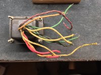
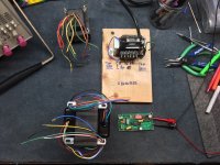
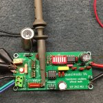
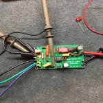
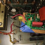
Here are some pics and I think I finally have the right capacitors and resistor value. But I'll leave that up to the folks here to guide me. It's taken me a little bit to figure out how to damp the ringing in my pre amp.
It has a split primary 240 and 120 VAC. That combined with 3 output pair feeding three full wave bridges. The preamp is working so the first few times were fruaght with WTF Over?
After some more reading and cogitating... including some figuring too, I ended up putting a shoring wire across the outlets as these are fed from the same 120V line.
Mark was warning about using the 12 to 24 inch long gator wire and clips, which in my case confirmed the issue.
Then, going from the HV output of the secondary, I used about 6 inch lengths of bus wire to the transformer input of the Quasimodo. The remaining secondaries, I removed the jumpers wires from them and soldered between them a 100 ohm resistor.
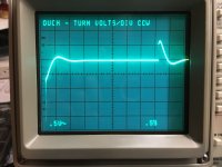
I'm using and old Tek 2246 scope, so I don't get the pretty pictures and all the features that you modern scope guys get. I can't zoom in either. When I go to enlarge my view by dialing down the volt/div, the scope gives me the "OUCH - TURN VOLTS/DIV CCW" message. Kudos
to TEK...it wasn't turn volts up or down, but specifically "turn counter clock wise." Which in itself will give digital kits fits. I can hear it now, "Clock wise, what is that? Sounds too old school and I'm a millennial...what do they know!"
okay moving right along. Keep in mind that if you can't zoom in too much at least for me, my scope was that the edge. Then adjusting time... kind of surprised me that some go down and other's go up....
Then realizing...the square wave, we are triggering on the fall
time...but also there is an equally fast rise time. Okay good, my board and device wasn't melting down.
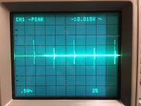
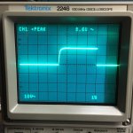
Here are are few pics from left to right:
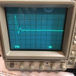
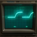
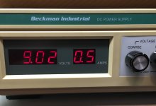
Here is the start, showing the square wave with a 8.6V peak.
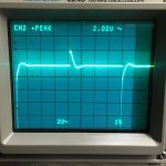
2nd pic of the rise peak 2.00V.
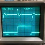
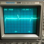
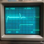
3rd pic shows the falling peak -23.04 V
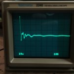
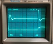
4th pic shows both the "square wave and the ringing transformer close to damped. Note it's 26V pk-pk from and 18V input.
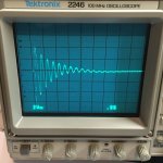
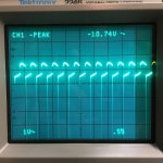
5th pic rings from the rising strike and the falling strike of Q-Modo.
6th pic dialed in the damping along with the square wave at 60 Hz.
It has a split primary 240 and 120 VAC. That combined with 3 output pair feeding three full wave bridges. The preamp is working so the first few times were fruaght with WTF Over?
After some more reading and cogitating... including some figuring too, I ended up putting a shoring wire across the outlets as these are fed from the same 120V line.
Mark was warning about using the 12 to 24 inch long gator wire and clips, which in my case confirmed the issue.
Then, going from the HV output of the secondary, I used about 6 inch lengths of bus wire to the transformer input of the Quasimodo. The remaining secondaries, I removed the jumpers wires from them and soldered between them a 100 ohm resistor.
I'm using and old Tek 2246 scope, so I don't get the pretty pictures and all the features that you modern scope guys get. I can't zoom in either. When I go to enlarge my view by dialing down the volt/div, the scope gives me the "OUCH - TURN VOLTS/DIV CCW" message. Kudos
to TEK...it wasn't turn volts up or down, but specifically "turn counter clock wise." Which in itself will give digital kits fits. I can hear it now, "Clock wise, what is that? Sounds too old school and I'm a millennial...what do they know!"
okay moving right along. Keep in mind that if you can't zoom in too much at least for me, my scope was that the edge. Then adjusting time... kind of surprised me that some go down and other's go up....
Then realizing...the square wave, we are triggering on the fall
time...but also there is an equally fast rise time. Okay good, my board and device wasn't melting down.
Here are are few pics from left to right:
Here is the start, showing the square wave with a 8.6V peak.
2nd pic of the rise peak 2.00V.
3rd pic shows the falling peak -23.04 V
4th pic shows both the "square wave and the ringing transformer close to damped. Note it's 26V pk-pk from and 18V input.
5th pic rings from the rising strike and the falling strike of Q-Modo.
6th pic dialed in the damping along with the square wave at 60 Hz.
Attachments
Last edited:
The Rest of the Pics
And here are the rest of the pics:
MJ requesting that we include a 600Hz pic by switching pin 1 of dip. Zeta = 1.
OUCH - Turn CCW...as I try to zoom in. I cannot,
The view of both the square wave and the damped ring on the fall.
I dialed the voltage down from 18V in the prior series of pics. If you notice the VPk-Pk was quite large and my scope didn't like it. So I dialed it down to about 9V.
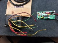
Last pic is how I wired it into my ARC SP3-A1.
The result: Cs = .47uf/630V Cx = . 47uf/630V Rs = 54 Ohms.
The pot was removed from Q-Modo for measuring. Also note the large R2s...I added a 1kohm across the 4.7kohm yielding about 825 ohms for R2. I'm not running on a battery and it helps me see the trace on the old scope.
Also note the damping resistors on the the other two secondaries. If you look closely you will see dot's on the board and wires. I used MJs phase dot jig to ID and set it up correctly.
Curiously, the third (yellow) secondary is wired out of phase with the the other two. I don't know what affect this has on the pre amp. If anyone cares to explain, I'm all ears as I'm sure others would be interested also.
Cheers,
And here are the rest of the pics:
MJ requesting that we include a 600Hz pic by switching pin 1 of dip. Zeta = 1.
OUCH - Turn CCW...as I try to zoom in. I cannot,
The view of both the square wave and the damped ring on the fall.
I dialed the voltage down from 18V in the prior series of pics. If you notice the VPk-Pk was quite large and my scope didn't like it. So I dialed it down to about 9V.
Last pic is how I wired it into my ARC SP3-A1.
The result: Cs = .47uf/630V Cx = . 47uf/630V Rs = 54 Ohms.
The pot was removed from Q-Modo for measuring. Also note the large R2s...I added a 1kohm across the 4.7kohm yielding about 825 ohms for R2. I'm not running on a battery and it helps me see the trace on the old scope.
Also note the damping resistors on the the other two secondaries. If you look closely you will see dot's on the board and wires. I used MJs phase dot jig to ID and set it up correctly.
Curiously, the third (yellow) secondary is wired out of phase with the the other two. I don't know what affect this has on the pre amp. If anyone cares to explain, I'm all ears as I'm sure others would be interested also.
Cheers,
Attachments
Last edited:
- Home
- Amplifiers
- Power Supplies
- Simple, no-math transformer snubber using Quasimodo test-jig