Congratulations, andrensairr! I will edit post#1 of this thread and add your name to the list of brave souls who dared to send QM Gerber CAD files to a fab, and ordered their own PCBs.
Your waveforms look very nice and of course I applaud your choice in oscilloscopes.
As for the alarming value of Rsnub, take a look in another thread (linked below) and see what other Quasimodo users have found for the optimum zeta=1 value of Rsnub, across a reasonably large number of transformers:
You might also enjoy studying the spreadsheet in post #593 of this very thread, compiled by member DNi.
BTW I resided in a US town called "Scottsdale AZ" for a number of years. That guy Scott must have been quite a traveler.
Last edited:
It would also be helpful if recent "club member" additions could add their results to the above-linked thread.
So far I have two results that I have confidence in for the Yellow and the orange pair of secondaries for the SP3-A1 power transformer.
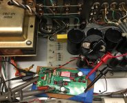
I've reviewed the factry schematics and there is no snub/damp of the secondaries, Red, Orange, Yellow. Red is the B+ at 500V. I'm thinking the Orange and Yellow are for heaters. for the tubes. Orange goes to a few tubes and yellow goes to a few tubes. I'm not a fan of the ARCs schematic either. Pics soon.
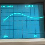
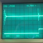
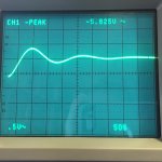
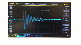
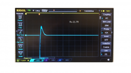
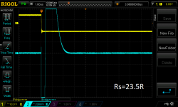
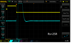
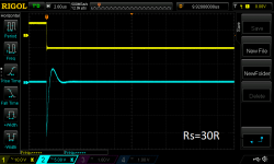
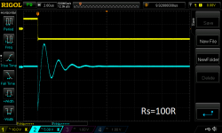
1st pic is the big 500 ohm pot. It just plane works. 2nd pic Oscillation by overdamping? just at the beginning but rather not see it. 3rd pic. Shows a damped ring. Too much or just right perhaps. 4th pic shows a reality check just to see what the sqaure wave look like and the ringing. 5th shows the amout I could damp before the wave becomes junk.
I'm no experpt at this but am learning. If anyone has comments please share.
I've reviewed the factry schematics and there is no snub/damp of the secondaries, Red, Orange, Yellow. Red is the B+ at 500V. I'm thinking the Orange and Yellow are for heaters. for the tubes. Orange goes to a few tubes and yellow goes to a few tubes. I'm not a fan of the ARCs schematic either. Pics soon.
1st pic is the big 500 ohm pot. It just plane works. 2nd pic Oscillation by overdamping? just at the beginning but rather not see it. 3rd pic. Shows a damped ring. Too much or just right perhaps. 4th pic shows a reality check just to see what the sqaure wave look like and the ringing. 5th shows the amout I could damp before the wave becomes junk.
I'm no experpt at this but am learning. If anyone has comments please share.
Attachments

Last edited:
My jig sanity test
Hi Mark and all,
I need your help to analyse my v4 jig test results.
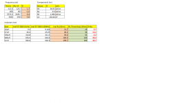
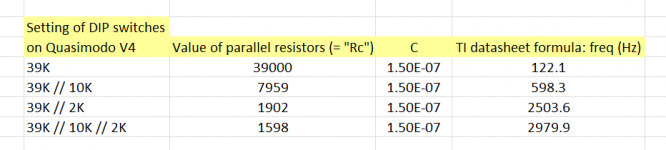
Please see attached table for M1 DRAIN frequency test with different switch positions and I assume that I'm in the ballpark. However, I do see some oscillations and it jumps to about 90Hz during 120Hz set (this flickering is exists in all tested frequencies): YouTube
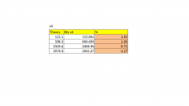
I checked some key components (also attached results the image) and I tested advised fixed (resistors look-like) inductors. As you see, I'm quite off from your calibration table. I do not think it is related to oscillations. What that difference cause might be? I used v3 jig with no oscillation, but Rs results are very similar.
Hi Mark and all,
I need your help to analyse my v4 jig test results.
Please see attached table for M1 DRAIN frequency test with different switch positions and I assume that I'm in the ballpark. However, I do see some oscillations and it jumps to about 90Hz during 120Hz set (this flickering is exists in all tested frequencies): YouTube
I checked some key components (also attached results the image) and I tested advised fixed (resistors look-like) inductors. As you see, I'm quite off from your calibration table. I do not think it is related to oscillations. What that difference cause might be? I used v3 jig with no oscillation, but Rs results are very similar.
Attachments

Last edited:
I wonder if it makes sense to add a snubber to a transformer feeding a resistive AC load, such as tubes heaters. What if the supplied tube is a directly heated rectifier?
Thanks for the advices!
Thanks for the advices!
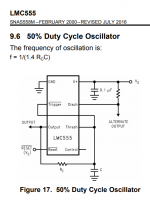
Your first error seems to be that you didn't use the proper equation from the LMC555 datasheet. Quasimodo's oscillator is the 1R, 1C, 50% duty cycle circuit which only works correctly with CMOS implementations of the 555. Fortunately the V4 Bill Of Materials calls for a CMOS 555.
The youtube video of misbehavior is horrifying. I would throw that board away and build another one.
_
The youtube video of misbehavior is horrifying. I would throw that board away and build another one.
_
Attachments
Last edited:
Thank you a lot for reply. Good news that captured in video misbehavior totally stopped when PSU dropped to 17.2VCD and below. It is 17.3 and up to 18 VDC that caused such issue. So, I set PSU to 15VDC and it is very stable now.
I'll remeasure all 4 switch positions with stable behave on Rigol DG4062 counter for precision and compare results to corrected TI datasheet table. Be back tonight.
I'll remeasure all 4 switch positions with stable behave on Rigol DG4062 counter for precision and compare results to corrected TI datasheet table. Be back tonight.
Hi Alex,
Yep, that sure is a darned interesting 'scope trace (YouTube).
Looks a lot like when a CMOS input is left floating, and being tormented by noise or a leakage path -- probably 50/60 Hz or a harmonic. Whatever the source, it pretty much has to be numerically related to the intended osc frequency to exhibit the 3 distinct periods. Might be a noisy florescent light or an incandescent on a dimmer.
I have no idea why it would behave below 17.3 Vcc, though .. Oh wait -- that would move the threshold on that (presumably floating) input.
If I understand your tables-of-values concerns, as long as they're within 1-1/2 percent or so, it's nothing to worry about. It certainly can't cause the jumpy osc periods. But there IS something to be said for OP's solution, too!
Hi SyncTronX,
Your 500 ohm pot looks like a vintage wirewound, which might have a minimum value as high as 3 - 5 percent. The 'zeta=1' value you need may be less than 25 ohms, and as big and beautiful as that pot is, it may not go that low.
If your Tek 2246 continues to work as well as mine, it'll still find a lot of problems for you. The 1 M ohm/20 pF is just the input rating; subsequent stages can still be overloaded.
Hi fralippo,
I would say no for both cases: As long as there is no rectifier to continue conducting as it goes from forward to reverse biased -- after it's supposed to have already turned off -- there's no 'hammer to ring the bell'.
Cheers,
Rick
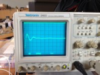
Just wanted to show my bona fides as another member of the antique Tek fan club. (And yes, that is an undamped Quasimodo trace, just to keep things on topic.)
Nice Tektronix scope Jeff - I guess it’s antique but it’s just a baby compared to the 465M I have. 🙂
Hi Rick and all,
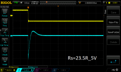
I feel we got kind of consensus abut my jig correct frequency respond and general functionality. Now question is why my 10uH (and the rest of my 5% conductors from DigiKey) test is so deviated from Mark's "golden test" table. Am I doing something wrong (please see attached images with R chronology (from high to low))?
I feel we got kind of consensus abut my jig correct frequency respond and general functionality. Now question is why my 10uH (and the rest of my 5% conductors from DigiKey) test is so deviated from Mark's "golden test" table. Am I doing something wrong (please see attached images with R chronology (from high to low))?
Attachments


Nice!
They'll have to pry my 2465 from my cold, dead hands ...
mlloyd1
They'll have to pry my 2465 from my cold, dead hands ...
mlloyd1
Just wanted to show my bona fides as another member of the antique Tek fan club. (And yes, that is an undamped Quasimodo trace, just to keep things on topic.)
Remove the trimmer (giving Rs = Infinity) and try it on an inductor whose value is known; anything greater than 50 microhenries.
Please indicate any and all parts of this suggestion, that are unclear or difficult to understand.
Nice Tektronix scope Jeff - I guess it’s antique but it’s just a baby compared to the 465M I have. 🙂
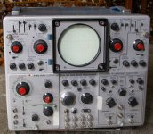
My large, antique Tek scope. Too lazy to drag it out to use with my Quasimodo. Actual independant dual beams, two scopes in one!
BTW, I have used my Quasimodo on dozens of transformers now, all with good consistent results. Thanks again Mark!
Take care,
Doug
Attachments
Please indicate any and all parts of this suggestion, that are unclear or difficult to understand.
Hi Mark,
Is this massage for me?
Alex
I'm a little confused, too -- your 'scope traces look letter-perfect to me, Alex.
Jeff, Bfpca, Doug -- salutations(sp?), that's some fine looking gear. And thanks for the 'confession', Jeff. Was kinda hoping we could persuade SyncTronX to not feel so bad about using a 30-year-old machine. I still use mine.
And I forgot a couple things from your post #1450, SyncTronX: You're right about the 0.5 A -- way too high, probably from the 30V Vcc exposure, no matter how brief. The NTD4906, like most MOSFETs, has a maximum Vgs rating of 20V. The delicate gate oxide is easily damaged and it would happen in just nanoseconds. Also, its max Vds rating is only 30 V, so the inductive kick from the 'first strike of the hammer' would exceed that rating, too. See if the board still draws 1/2 an amp after you remove the NTD4906. Something's got to be getting pretty toasty.
As far as the 0.5V version goes, the -555 and both versions of the buffer/driver circuit will work fine on 6 - 12V. Then provide the high side of the 4k7 resistor at the output with the lower voltage, maybe 0.4 to 0.7* V, and have at it. And you may want to try a smaller resistor -- say 1k or 2k2 -- just to get a cleaner trace.
A satisfactory pulse generator could be such a similar inexpensive, uncomplicated circuit -- depending on your needs. This circuit is exTREMEly low output impedance, lower than any pulse generator I've ever seen. Also most PGs have approximately symmetrical drive capability, like the MCP1407. Its output would likely be adequate for at least few PG uses. But you'd be giving up things like Trigger, Delay, Hold Off, Polarity, Amplitude and probably other features.
As is, the Drain of the NTD4906 has a much faster falling edge than the rising edge since the latter is provided by the 4k7 resistor. I'd personally be surprised if you needed a faster falling edge than that Drain, but your mileage may vary.
* If the xformer feeds a standard bridge rectifier, you could use up to 1 Volt, as long as you don't mind ignoring a flattened peak here and there. Would depend on the capacity and leakage of the big filter cap the bridge feeds.
Cheers,
Rick
Last edited:
Rick you could work backwards through all of the "I put transformer XX on my Quasimodo and got results YY" in the Quasimodo Results thread and calculate the effective leakage inductance of each one. In fact post #8 of that thread suggested the idea.
A quick and dirty spreadsheet will give you the resonant frequency of the LC circuit, formed by the transformer leakage inductance and the across-the-secondary snubbing capacitor Cx (=0.01uF in almost everyone's measurement setup).
Voila! Scan for the highest resonant frequency of them all and save the number. This gives you a quick way to estimate the fastest required risetime or fall time of the Quasimodo bellringer's hammer. For grubby simplicity, approximate the resonator's sinusoidal waveform by a triangle wave. Aha, that makes it easy, the ringing waveform's rise time is less than or equal to approx (1/(4*f)) seconds.
Now be a good engineer and kill a mosquito with a bazooka, just to make sure it's dead. Build your pulse generator with a rise time 10X faster than the risetime of the oscillatory sine wave. Presto, guaranteed to work, and with a very comfortable margin of safety too:
I predict you'll get a risetime number that's easy to achieve in practice, even with thru hole components plugged into solderless breadboards. As long as you keep the ground wires short and the supply bypass plentiful.
A quick and dirty spreadsheet will give you the resonant frequency of the LC circuit, formed by the transformer leakage inductance and the across-the-secondary snubbing capacitor Cx (=0.01uF in almost everyone's measurement setup).
- f_resonant = (1 / 2pi) * [1 / sqrt(L*Cx)]
Voila! Scan for the highest resonant frequency of them all and save the number. This gives you a quick way to estimate the fastest required risetime or fall time of the Quasimodo bellringer's hammer. For grubby simplicity, approximate the resonator's sinusoidal waveform by a triangle wave. Aha, that makes it easy, the ringing waveform's rise time is less than or equal to approx (1/(4*f)) seconds.
Now be a good engineer and kill a mosquito with a bazooka, just to make sure it's dead. Build your pulse generator with a rise time 10X faster than the risetime of the oscillatory sine wave. Presto, guaranteed to work, and with a very comfortable margin of safety too:
- Pulse_generator_risetime <= [1 / (40 * f_resonant_highest_of_all_transformers)]
I predict you'll get a risetime number that's easy to achieve in practice, even with thru hole components plugged into solderless breadboards. As long as you keep the ground wires short and the supply bypass plentiful.
Hi Rick,
Thanks for the suggestions. It was only drawing that much current then. I haven't calculated what the voltage drop would be across the NTD4906. I do have a few spares.
So if it was damaged...it might explain why I was having difficulty after that.
Also, in one of MJs earlier posts, I did put a 1k resistor in parallel with the 4K7 resistor. I think it ends up being something like 825 ohms there. Not battery operated and it does help the trace to show up.
Recall, that transformer is a 500V unit which supplies current for 7 12ax7a's operating at 12.6V is 150mA each. So 150mA x 7 = 1,050 mA.
Designed for a little more juice then driving smaller chips. This is only
a pre amp and not an Amp amp. I don't even know if that makes sense.
Cheers,
- Home
- Amplifiers
- Power Supplies
- Simple, no-math transformer snubber using Quasimodo test-jig