Thanks Mark. Not just for this entry -- the whole huge investment you've made in this clever little bit of kit. And still with a sense of humor. Hope it isn't starting to feel like an anchor chain around your neck! ;^) Much appreciated.
Regards,
Rick
Regards,
Rick
I'm a little confused, too -- your 'scope traces look letter-perfect to me, Alex.
Ah, thank you and I have very nice precision too. I ran x5 and got very tight (I can say -> same) results on several values of my reference coils.
Still big question about accuracy since its deviates from Mark's table. I must to finalize setups for 6 new transformers and I'm not sure.....
What else can be checked, tested or adjusted on it?
Thank you.
Alex
Hi Sync,
Is this the same gear we saw earlier with the red, yel, and org secondaries? I thought I remembered that each went to a clutch of 4 rectifiers connected as a full-wave bridge. So .. I hope your plan is to separately Q'modo each secondary. And otherwise, it does make sense.
Cheers,
Rick
Is this the same gear we saw earlier with the red, yel, and org secondaries? I thought I remembered that each went to a clutch of 4 rectifiers connected as a full-wave bridge. So .. I hope your plan is to separately Q'modo each secondary. And otherwise, it does make sense.
Cheers,
Rick
Hi Alex,
Sorry, but I'm still lost as to which table disagrees. Could you tell which post it is in so we're looking at the same thing.
Also, are you one of the folks using a larger than 0.01uF value for Cx?
Cheers,
Rick
Sorry, but I'm still lost as to which table disagrees. Could you tell which post it is in so we're looking at the same thing.
Also, are you one of the folks using a larger than 0.01uF value for Cx?
Cheers,
Rick
I have to remind myself that Quasimodo V1 was limited to a 5V (not 9V, not 18V) power supply, so its electronic switch SW1 had a lot less "drive" on the control signal, to make it switch quickly. I have to remind myself that Quasimodo V1 used, out of desperate necessity, a Hex Inverter Digital Logic Gate (not a dedicated MOSFET gate driver chip) whose output current was a scrawny 0.1 amperes. By contrast, the shipped-to-customer revisions of Quasimodo had a 1.5 ampere gate driver chip in V3 and a 6.0 ampere chip in V4. As they remarked on the TV show "West Wing", that would be less. A lot less.
And yet Quasimodo V1 worked; it was Good Enough. I have to remind myself that Quasimodo V3 and V4 are more than Good Enough. And sometimes I giggle at incoming queries about the outer limits of its pass/fail envelope; most often the inquirer has done little to no estimates or calculations, not even on the back of a napkin from a drinking establishment whose main distinguishing feature is: minimally clothed employees.
_
Attachments
Hi Alex,
Sorry, but I'm still lost as to which table disagrees. Could you tell which post it is in so we're looking at the same thing.
Also, are you one of the folks using a larger than 0.01uF value for Cx?
Cheers,
Rick
Hi Rick and Mark,
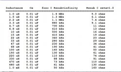
I use 0.01 for Cx and 0.15 for Cs. Two boards are tested: V3 (SMD) and V4 (through-hole). PSU is HP E3617A and it is set to 0-15VDC. I attached table which I used for reference. I found it in the post 487 when Mark described testing methode. All my instructors purchased from DigiKey.
I purchused: 10uH/47uH/330uH/680uH/1mH
Here is the link: https://www.digikey.com/products/en...e=0&rohs=0&quantity=3&ptm=0&fid=0&pageSize=25
Attachments
Last edited:
Hi Mark,
Glad it is a giggle and not a blown brain fuse.
No such queries from me, I hope. Besides, I'm kinda fond of Quasimodo V1 and its Hex Inverter driver. But hey, if you can have a 99-cent part that can slew 2500pF rail- to-rail in 20 nanosecs with an 18V supply, why not? And if we get to learn some basic electronics while doing something that improves our gear, so much the better.
Thanks again Mark, Rick
P.S. I make no confessions concerning design ideas on bar napkins.
Hi Alex,
O.K. Thanks. I'll have another look at your 'scope traces to see if I can sift out what is still giving you trouble.
Regards,
Rick
Hi Alex,
Checking your post #1472, the first 'scope trace shows the ringing at almost exactly 500 kHz -- each cycle occupies one division of 2 microseconds. The value from the table in post #487 for 10uH with 0.01uF is also 500 kHz. For 5% and %10 parts, that seems pretty good to me.
Granted, your derived zeta=1 value for Rs is higher, 23.5 ohms rather than the table-predicted 16 ohms. This is not a surprise, though, since each part contributes its own small losses to the result.
But this is exactly what makes Quasimodo so great! All those pesky little parasitic factors that are hard to measure even with expensive equipment and setups, can be completely ignored: They're fully accounted for by the method!
In sum, I think your Quasi is working perfectly. Snub away!
Cheers,
Rick
Hi Rick,
Really appreciate your feedback. All what you say is make sense and I just was not sure since I thought that I'm doing something wrong. Going to use it evasively now (thanks to Mark for that jig). Have to finish 4 UltraBIB Salas destined PSUs for Allo made Katana DAC. 🙂
Really appreciate your feedback. All what you say is make sense and I just was not sure since I thought that I'm doing something wrong. Going to use it evasively now (thanks to Mark for that jig). Have to finish 4 UltraBIB Salas destined PSUs for Allo made Katana DAC. 🙂
Apologies for my misspelling.
iPhone autocorrection is messing up some words in the way that makes antonyms of them.
I tried to say that I will use it widely now. Thank you again.
iPhone autocorrection is messing up some words in the way that makes antonyms of them.
I tried to say that I will use it widely now. Thank you again.
I’d love to have one of the Quasimodo boards as well!
Also, a friend of mine loaned me his SMD Quasimodo board, but I’ve been having some problems getting it to work (at all).
It is hooked up per the guide. I am using a dual channel Tek 465b, a bench supply set to 12v to power it. Both transformers I’ve tried it on are dual secondary; one is dual primary. Primaries shorted, other secondary shorted. The trigger waveform looks fine but I’m not getting any output. If I disconnect the secondary from the Quasimodo, the output matches the input. Connected I get nothing. I removed the pot, still no change. I’m thinking it is the STS chip (don’t recall the number) which drives the output.
Any thoughts?
I was mistaken, it lives! I wasn't triggering correctly or at least looking at the right thing. I got a couple of inductors (4.7mH) and matched BigE's results exactly from post 488. I had also tossed together a cheapomodo since I had all the parts laying about, so that taught me what to look for on the scope, for the most part. Building my own thru-hole version currently, and seeing how bad my scope needs recapping and new probes 🙂Remove the trimmer (giving Rs = Infinity) and try it on an inductor whose value is known; anything greater than 50 microhenries. You should see a waveform similar to Figure 12 in the Quasimodo design note. If you don't, apologize to your friend for destroying his Quasimodo V3.
I still haven't read the entire thread yet, but did have a couple of questions:
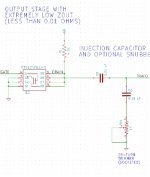
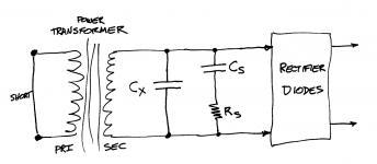
- I struggle to see how the quasimodo (pic 1), with the Cx cap in series with the load, equals the actual snubber (pic 2), with Cx in parallel to the secondaries? I know the mosfet acts as a switch and is very low impedance, but it doesn't seem equivalent...
- From what I have seen I think this is correct, but the quasimodo jig won't function with Cx replaced by a jumper, i.e. I want to see what a simple RC snubber would look like? Or does the jig work OK that way?
Attachments
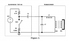
A transformer + snubber + diodes is shown in Figure 1 below. In operation, the diodes inject an (unwanted!) pulse into the circuit, every time they turn off, causing oscillatory ringing.
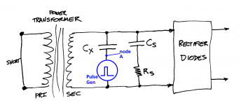
Figure 2 below shows the same circuit, attached to Quasimodo. Quasimodo is the blue circle on the schematic. Now Quasimodo injects a pulse into the circuit, causing oscillatory ringing.
The Quasimodo circuit works quite well, precisely because Quasimodo's output resistance ("impedance") is incredibly low: 0.006 ohms. After Quasimodo injects its single step function pulse, it becomes an almost perfect, dead short. The blue circle becomes a more or less perfect conductor of negligible resistance. Thus Figure 2 is the same as Figure 1, after the pulse is generated and while the resonant circuit is ringing.
If anyone wishes to perform a small signal analysis of figure 2, I have labeled node A for your convenience. But I think the previous paragraph explains the situation well enough, without introducing scary undergraduate EE terminology.
_
Attachments
...And sometimes I giggle at incoming queries about the outer limits of its pass/fail envelope; most often the inquirer has done little to no estimates or calculations, not even on the back of a napkin from a drinking establishment whose main distinguishing feature is: minimally clothed employees.
Aww, heck MJ, er, ah, I'd be too embarrassed to post those pics of mine on the back of the napkin from... Fredrick's of College Station! "Where men are men and sheep are scared." I'm having a hard enough time of just keeping up with my
2-D Kinematic vector analassit equations in my Physics for Dummies course at my local C.C.--let along trying to regurgitate all ruminating stuff.
Hmmm, now I'm wondering if the bar-naps in those places come with two indentations so that when you open up the bar-nip they are evenly situated among the two halves. Looks like I'll have to raid the penny jar and head out to "Wally-World" and use the machine there to exchange the pennies for dollar bills. This Aggie is on a Mission.
Cheers,
Just wanted to show my bona fides as another member of the antique Tek fan club. (And yes, that is an undamped Quasimodo trace, just to keep things on topic.)
Jeff, I have to ask are you powered up with Irish 230V 50Hz power? I haven't looked if they come with US or Int'l transformer versions. OR are they SMPSs in there.
Cheers,
Hi Sync,
I can't speak for Jeff, but my 100 MHz Tek from 1987 is SMPS, and the back panel says it doesn't mind 90 to 250V, 48 to 440(!)Hz.
(Darn -- just realized this doesn't qualify as On Topic.)
Regards,
--Rick
I can't speak for Jeff, but my 100 MHz Tek from 1987 is SMPS, and the back panel says it doesn't mind 90 to 250V, 48 to 440(!)Hz.
(Darn -- just realized this doesn't qualify as On Topic.)
Regards,
--Rick
Rick,
Yes, that is what I've been doing. Q-Modo-ing each secondary separately. Red, orange, yellow.
I'm pretty sure I have the orange and yellow accomplished properly. Red, while I thought I had it I still have some uncertainties about it.
So the pre amp was put up for the time being as I have to finish up the bench shelves...which turned out to be a nightmare. I'm still battling it. to change anything, I have to disconnect the lower shelves toget to the upper shelves. Have to add deeper shelving to hold the parts bins. Have to raise shelves to accommodate the test gear.
Have to make the lighting board adjustable, pull-in and pull-out so I don't get LED glare in my eyes.
LED Glare is becoming more and move of an issue with me. Neighbors put up superbrite LEDs for porch lighting...which is blinding. Some stores have moved and new locations installed superbright LEDs everywhere. After being in the store a short time, I had to leave. Headaches, eye pain, extreme fatigue overcame me quickly. At least my LED strips are dimmable and will have a front shield so it won't shine in my eyes.
Cheers,
Power supply regulation?
How to make a simple power supply regulator that would track the variable DC VCC in from say 3VDC to 20VDC, then when it reaches 20VDC it stablizes it from going higher?
Maybe something like a zener that when the VCC hits +20.2V it will start bleeding off the higher voltage...to somewhere, but not sure where.
Not sure if I said that correctly or not?
Cheers,
Hi Sync,
I can't speak for Jeff, but my 100 MHz Tek from 1987 is SMPS, and the back panel says it doesn't mind 90 to 250V, 48 to 440(!)Hz.
Regards,
--Rick
Yep, mine has a switch on the back for 110/230.
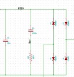
I tossed together a cheapomodo on solderless breadboard to mess around with, seemed to work alright even though it is a mess:

Built a through-hole board on the board and MOSFET supplied to me by yoaudio (thanks!).

Transformer: ILP 49783R1 - 1014, 160Va, dual secondaries
Undamped (10nf Cx)

Damped 10nf Cx, 150nf Cs, Rs ~12R

Same transformer, John Swenson RC snubber 330R/22nf

Not bad, much better than no snubber, though a bit underdamped (I think?).
Built a through-hole board on the board and MOSFET supplied to me by yoaudio (thanks!).
Transformer: ILP 49783R1 - 1014, 160Va, dual secondaries
Undamped (10nf Cx)
Damped 10nf Cx, 150nf Cs, Rs ~12R
Same transformer, John Swenson RC snubber 330R/22nf
Not bad, much better than no snubber, though a bit underdamped (I think?).
Congratulations upon your success!
You may find it useful to fervently study the oscilloscope manual, to find out how to slide the trace left and right. That will let you put the triggering point at roughly 25% of the trace width. Then you can see all of the undesirable, but very real, artifacts of a more than zero-nanohenry grounding network. It'll also make it easier to count the oscillatory ringing lumpity bumps and to observe them slowly disappear as you slowly dial the trimmer.
It may well be that 330R might give better-than-nothing-at-all results with high voltage transformer secondaries in vacuum tube equipment. But as the other diyAudio thread called "Quasimodo results only" repeatedly demonstrates, 330R is absolutely the wrong value for sub-60VAC secondaries on toroidal transformers, as used in lots of solid state power amplifiers. I bet that you and John Swenson could do a "quick" (< 3 day) simulation study to find out what might be the least worst option for a 1C+1R+no_adjustments snubber for solid state gear. Best of all, the simulator barfs out quantitative information, telling you how bad it can be in the worst case.
Thanks Mark,
I don't know John and regardless, that isn't happening. His recommendation came around 2010 IIRC, way before your cool board and method without calculations, and was from his empirical observations and meant to be a universal swag. On the scope, with two decidedly SS gear transformers, the results are certainly much better than no snubber at all, and is what I have been using pretty much since I read it.
In the future, I will use what I arrive at using the Quasimodo, but for non-critical applications, may continue to use the 330R/22nf (since I have a bunch of MKP1837 22nf caps).
I had never used delay triggering, etc. in my 5 years as a tech at a semiconductor manufacturer back in the early-mid '80s, so I took a look at a video or two last night to see if I could delay the triggering long enough to put the negative edge more into the scope center (or 1/4 way from the left). My first pic shows some of that on my Tek 465b. I'll play around with that some more, and just received a Tek 2465a tonight, so I'll be curious to see what it can do.
Thanks again for the Quasimodo theory and circuit/boards in raising awareness that the typical 0.01uf cap across the diodes <> snubber!
- Home
- Amplifiers
- Power Supplies
- Simple, no-math transformer snubber using Quasimodo test-jig