RE: Post #18, this thread.I also built a prototype of Quasimodo on solderless breadboard, and it worked quite acceptably: see photo here. The "gate driver" was six 74AC04 logic inverters connected in parallel, giving 6 x 24mA output current.
Hi Mark,
I know this has been a while since you bread boarded this, but any changes we should know about? I assume they are in the first post? Does it have all the cap values also?
Cheers,
Cheapomodo post #187 attaches a Veroboard / Stripboard cuts-and-jumps map, which implements Cheapomodo V3. The schematic for V3 is presented in Cheapomodo post #132, and so are the PCB CAD Gerber files.
If you prefer Thru-Hole Quasimodo V4, its schematic and PCB Gerber files are attached to post #1 of the Quasimodo thread which you are reading right now. Same is true of SMD Quasimodo V3.
V3 is the latest Cheapomodo and V4 is the latest thru hole Quasimodo.
Several people have succeeded with a solderless breadboard implementation too. If you go this route I recommend cutting solid core hookup wires to length and stripping them yourself, rather than using those storebought all-one-length pluggy wires with stiff tip connectors. You don't want excessive amounts of inductance in the ground path, or in the drain-to-Cx-to-Trafo, so keep those leads short. Cut to required length and no longer.
Attachments
Thanks Mark,
Rooting around here I don't have the 2n7000s. But do have some 2sc2240s. Thinking I can just Follow your layout on M1, M2, M3. There are slight variations that I see from quasi- and cheapo-modos. One that I see in layout only has Q1. Cheapomodo Schematic had Q1&Q2. The 2N3904/3906 pair. The vector board configuration (0-30; 0-18) only shows a Q1. Could I use a single 2N2222 can driving the 2sc2240 x 3? Along with slots for inserting Cs and Cx.
Trying to work with what I have around here or what is at the local discount ELE supply house.
Cheers,
Last edited:
This may have already been addressed somewhere deep in the thread... From my understanding toroids have two drawbacks:
Ringing
Stray fields
While the Quasimodo addresses the first, has much ink been spilled on quantifying the second? I.e. how much steel to mitigate stray fields for a given VA rating? My guess is that these two forces combined together, would make for a whole lot less pricey umbilicals and psu chassis being assembled. Am I wrong? Can someone point me to some kind of articulated addressing of the stray field issue? Mostly I simply see confirmation of its existence and general rules of thumb for distances from sensitive circuitry.
Hi SyncTronX,
Hope I'm not sticking my big snout in where it doesn't belong, but having now read every .. single .. post in this thread, I feel at least 'marginally qualified' to tackle this one, and save Mark the effort -- providing neither of you object . . .
A couple things worry me: "don't have the 2n7000s. But do have some 2sc2240s", and "Could I use a single 2N2222 can driving the 2sc2240 x 3?"
1) The spec'd output device(s) really needs to be a MOSFET. Otherwise the result will disappoint. Remember you're hitting a 'hard' circuit, forcefully, with a 'hammer'. A bipolar device cannot turn on as fast or hard -- single-digit-milliOhms -- and requires a completely different drive circuit.
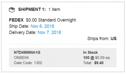
[t]Arrow.com still has 41k of NTD4906's, at prices so cheap you'd have to buy 25 ($3.70) or 100 ($9.40) of them just so the shipping/handling charges don't swamp the component cost! You could have them in ~5 days, and sell the extras to your friends -- our other members! DigiKey.com and Mouser.com have fitting subs, as well.
2) Whatever you decide to use for output(s)(the 'hammer'), dig out a PNP for the driver. 555 timers provide 4 to 5 times higher current Sinking than Sourcing, and you need to multiply that by PNP current gain to have any reasonable chance of turning on ANYthing hard enough. An emitter-follower NPN (such as the venerable 2N2222) simply won't do it.
Maybe it's my ego showing but, I suggest that you just surrender to the 4 or 5 day wait for the right part, and you'll be a lot happier with the result. Plus, you won't have to spend a few hours redesigning the drive circuit!
Best Regards,
Rick
Hope I'm not sticking my big snout in where it doesn't belong, but having now read every .. single .. post in this thread, I feel at least 'marginally qualified' to tackle this one, and save Mark the effort -- providing neither of you object . . .
A couple things worry me: "don't have the 2n7000s. But do have some 2sc2240s", and "Could I use a single 2N2222 can driving the 2sc2240 x 3?"
1) The spec'd output device(s) really needs to be a MOSFET. Otherwise the result will disappoint. Remember you're hitting a 'hard' circuit, forcefully, with a 'hammer'. A bipolar device cannot turn on as fast or hard -- single-digit-milliOhms -- and requires a completely different drive circuit.
[t]Arrow.com still has 41k of NTD4906's, at prices so cheap you'd have to buy 25 ($3.70) or 100 ($9.40) of them just so the shipping/handling charges don't swamp the component cost! You could have them in ~5 days, and sell the extras to your friends -- our other members! DigiKey.com and Mouser.com have fitting subs, as well.
2) Whatever you decide to use for output(s)(the 'hammer'), dig out a PNP for the driver. 555 timers provide 4 to 5 times higher current Sinking than Sourcing, and you need to multiply that by PNP current gain to have any reasonable chance of turning on ANYthing hard enough. An emitter-follower NPN (such as the venerable 2N2222) simply won't do it.
Maybe it's my ego showing but, I suggest that you just surrender to the 4 or 5 day wait for the right part, and you'll be a lot happier with the result. Plus, you won't have to spend a few hours redesigning the drive circuit!
Best Regards,
Rick
Last edited:
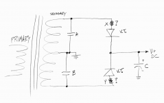
For diode capacitance, the lowest capacitance rectifier I've encountered is the lowly 1N4005, at 8 picofarads. The highest capacitance rectifier diode I've encountered, is the VF30100S, at 2700 picofarads (!!), pictured below.
_
May I ask: Are there any measurements/experiences on the capacitance of tube rectifiers as well...thinking about the first C as 10nF...still the right ball park for the game with HV secondaries and tube rectifiers ?
I am still reading...first 400 threads done and used the search function, but did not find anything...
Maybe a second question is allowed as well: I saw the recommendation for a battery-powered osci from banggood...was this just for convenience ? So will any other DSO which is not battery powered be fine as well ?
Thx a lot, what a great project.
I used it with a 180V secondary and voltage-doubling rectifier (for a 400V B+) and got:
Cx: 0.01uF
Cs: 0.1uF
Rs: 464Ω
And with a 200V secondary, full-bridge rectifier and capacitance multiplier (for a 225V B+) and got:
Cx: 6,800pF
Cs: 0.068uF
Rs: 825Ω
Note that in the second case I used different cap values just because I was raiding my spares box.
Cx: 0.01uF
Cs: 0.1uF
Rs: 464Ω
And with a 200V secondary, full-bridge rectifier and capacitance multiplier (for a 225V B+) and got:
Cx: 6,800pF
Cs: 0.068uF
Rs: 825Ω
Note that in the second case I used different cap values just because I was raiding my spares box.
Hello member Blitz, please have a look at this thread
Capacitance of rectifier tubes/valves near V=0??
Capacitance of rectifier tubes/valves near V=0??
Mark, thanks a lot...I have read through it. So, the 10nF stays.
I do nit subscribe to the theory that tube transformers do not need snubbers as it has been expressed by some in that thread...I will build your quasimodeov4 (once I got the kit I ordered today) and test my Xformers...and will report back.
I do nit subscribe to the theory that tube transformers do not need snubbers as it has been expressed by some in that thread...I will build your quasimodeov4 (once I got the kit I ordered today) and test my Xformers...and will report back.
I have just found this very interesting thread and would like to use a Quasimodo for optimizing my power supply. I am wondering if anybody has a new or used finished Quasimodo V4 for sell?
Cheers,
Roland
Cheers,
Roland
I noticed a pretty good deal at electronics distributor arrow.com just now. They are selling the Thru Hole Quasimodo ("V4") power MOSFET for a very low price: USD $0.0094 each, in quantity 100. So I bought 100 pieces and got free shipping too!
Take advantage of this while you can. They only have forty thousand pieces in stock.
_
Take advantage of this while you can. They only have forty thousand pieces in stock.
_
Attachments
That is pretty good Mark, thanks for the heads up. I guess I have a life time supply of those little critters.
Question, For Cheapomodo, what did you use to do your perf board layout with? By chance do you have non-populated versions of the perf board Component side and the "trace" sides?
I want to try a Quasimodo V4 perf board layout...for some reason. I don't want to mangle what you've already spent time doing either.
Cheers,
Mark, May I ask you for your thoughts on the following:
When you use mercury tube rectifier (which can sound extremely nice), you can find in the old data sheets the advise to have
- a cap from sec.winding / anode to CT in the magnitude of 1n to 10n
- and / or a choke between secondary and anode of the rectifier in the magnitude of 1mH or more (see https://frank.pocnet.net/sheets/021/8/82.pdf)
The 10nF is part of your standard snubber setup...but what about a 1mH choke ? Put it on the secondary and fine tune the snubber including the choke I would guess, no ?
Blitz- it is worth noting that Mercury Vapor recruiters emit very, very high amounts of UV. Enough that you may want to consider if you want them where you are exposed to the glow.
If its a lot of UV, I guess it would be good for disinfection duties. Just as long as the rectifier doesn't break when operating.Blitz- it is worth noting that Mercury Vapor recruiters emit very, very high amounts of UV. Enough that you may want to consider if you want them where you are exposed to the glow.
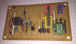
Still working on that 'Modo-4 vector board layout. Now, if I can just figure out where all the extra .1uf caps go.... and the big220uf cap and wire in the 4 switch dip and I only have 18 horizontal lines and have to make sure not to cut the hook up wires too short for and extended horizontal line or two.
I think I can.
Cheers,
Last edited:
- Home
- Amplifiers
- Power Supplies
- Simple, no-math transformer snubber using Quasimodo test-jig