Jamesblond, there is a 22 page Design Note attached to post#1 of this thread. It talks about Quasimodo in great detail. It also includes hyperlinks to other technical papers about transformer snubbing, notably Hagerman's and Cornell Dubilier's. A wealth of snubber information is available to energetic students.I'm still quite a newby, so I'd like some help.
If you want someone to explain the diyAudio store's Universal Power Supply Board, I'm sure there is a forum dedicated to it somewhere. I'm confident they'll tell you that if you completely omit the transformer snubber, your power supply board will still work and will still supply power. It may have a splash of ultrasonic oscillations in the secondary, whose audible effects may or may not be significant. Remind yourself that many high end audio products have no transformer snubber at all, and yet they perform adequately & their owners are happy.
You can always go back and install the snubbing components later, after you've mastered AC circuit analysis, LTSPICE simulation, and laboratory procedures with an oscilloscope. The drill holes and copper traces on the PCB will still be there nine months from now. They'll be ready when you are ready.
Last edited:
The right answer for the schematic in post#608 is Cx = (2 * 22nF) = 44nF. That's what you'd use in Quasimodo testing of the transformer secondary. When you install the snubber you'd let those four capacitors work together to produce 44nF across the secondary, and you'd include an additional ZERO nanofarad Cx capacitor in your snubber.
There are three ways you can confirm or refute this answer: (i) pencil and paper analysis using Laplace Transforms; (ii) laboratory measurements of real power supplies; (iii) simulation. If you've got grave doubts about the right answer 44nF above, and if it is very important to you, then you can get busy with (i) , (ii) , or (iii) .
Thanks for your note.
My schematic is different from your drawing as in my schematic I had an extra Cx across the secondary. The caps across the diodes are 22nF and since there are 2 caps there the capacitance is 44nF according to your note. The Cx in my schematic is 22nF so the total is 2 x 22nF (from the caps across the diodes) + 22nF (from the cap across the secondary winding) = 66nF. Right?
Could you show your analysis here? Does simulation agree with it?
I did not analyse it... just thinking about.... Cx is in parallel with the capacitance of the rectifier... it should be much larger than the total rectifier capacitance so we could ignore the latter, but after the rectifier there is the smoothing cap (normaly).... should we not measure the TX ringing while it is connected to the rectifier bridge and also the smoothing cap ?
I did not analyse it... just thinking about.... Cx is in parallel with the capacitance of the rectifier... it should be much larger than the total rectifier capacitance so we could ignore the latter, but after the rectifier there is the smoothing cap (normaly).... should we not measure the TX ringing while it is connected to the rectifier bridge and also the smoothing cap ?
The smoothing cap has no effect on the frequency of the parasitic oscillations triggered by the rectifier diode's turning off.
You might wish to look at the oscillograms I attached to post #501, which were recorded in a working power supply. Shown in the first plot is the oscillogram of an unsnubbed transformer, and it is obvious that the frequency of the free oscillations does not correspond to a large smoothing capacitance (it would have been about 127Hz for a cap of 1000uF across that particular transformer's secondary).
Regards
Last edited:
Try it. Either on the bench using a real power supply, or in simulation using a simulated supply.... should we not measure the TX ringing while it is connected to the rectifier bridge and also the smoothing cap ?
I predict you'll discover that the damping factor Zeta does not change when you increase the smoothing capacitor value by 10X.
But ... maybe I'm not telling the truth ...
Try it and see for yourself. The experimental results will either strengthen your analysis, or weaken it.
I heard from somebody who found Appendix D confusing, specifically this part:
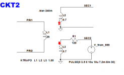
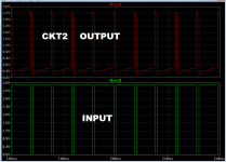
CKT2 applies the test signal to the dotted end of the lower winding, and attaches the scope probe to the not-dotted end of the upper winding. Notice how the output is upside down.
_
... a square wave with 10% duty cycle would work too. What you want is a waveshape that's easy to tell right-side-up from upside-down. Apply the test signal to the dot end of winding 1, and monitor winding 2 on the scope. If it's right side up then the scope probe is on the dot end of winding 2. If upside down, the probe's on the undotted end.
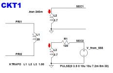
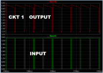
Attached are schematics and waveforms for two circuits. CKT1 applies the test signal (from a little NE555 oscillator circuit on your protoboard, or from your function generator) to the dotted end of the lower winding, and attaches the scope probe to the dotted end of the upper winding. Notice how the output os NOT upside down.CKT2 applies the test signal to the dotted end of the lower winding, and attaches the scope probe to the not-dotted end of the upper winding. Notice how the output is upside down.
_
Attachments
Thanks for clarifying that input is applied to a secondary and not to a primary. Cannot the Quasimodo supply the input, with a two-channel scope and one probe on Cx and the other on the second secondary? Yes, it's a 50% duty cycle but both should still be up/down at the same time.
A Pragmatic Question
Okay, I've read all 63 pages / 627 messages, of this thread, read Mark's documentation for Q'Modo, and ordered my Quasimodo V4 kit from dsolodov. But something's missing... 😕
Since the ultimate goal of this thread and its subject, Quasimodo, is to discover the proper snubber filters for our power supply transformers, may I suggest that we develop a running database of our findings? It can be a simple ASCII (Notepad) text file or an Excel spreadsheet, nothing fancy. Just a list of transformers and/or the equipment they're in, the snubber values Cx, Cs, Rs found, and perhaps a brief verbal observation of any sound differences we've perceived - knowing full well that snubbing a transformer isn't only a game for audiophiles who are not afraid of a soldering iron. 🙂
Just an idea, but it seems that we collectively have a lot of info sitting on the other side of the monitor that would be useful if published in this informal way. The "Nine Transformers" .pdf is a start, but we collectively need to add to it - I'm sure there's much more data available out there. 😉
That's my $0.02 and worth every penny you paid for it. 😀
create a database for quasimodo snubbers
Throwing my hat in for second attempt at creating a snubber database.
A new text file could be appended to an existing list.
transformer manufacturer, model name/number, prim Vac, sec1 Vac, sec2 Vac, VA, Cx, Cs, Rs, optional comments.
Just 10 comma separated data groups.
The 3 to 9 fields must be numbers and must be in the SAME order for every new transformer build AND must use the same units.
I would suggest that Cx and Cs be in nF (not pF and certainly not in uF)
If a new text file is for a single secondary transformer then a zero or other "dummy" number must be entered into field 5.
Easy to import into a spreadsheet.
Easy to re-order using the VA, or Rs, or any other of the NUMBER fields, as your first data sort
Last edited:
Please, do not use Google. They glean and mis-use more than enough of our personal information.Great idea, why not use a google docs spreadsheet for this ? much better than text file...
Who do they sell that information to? What does it get used for?
Last edited:
It is DarthBubba's idea
I just suggested a format.
may I suggest that we develop a running database of our findings? It can be a simple ASCII (Notepad) text file or an Excel spreadsheet
I just suggested a format.
Does everyone have access to Excel 2010, or something that can open an Excel spreadsheet?
I would keep the definition of "Manufacturer, model name, number" rather loose as I don't know who manufactured the transformer in the Hafler DH-101, but I'll bet everyone here knows which transformer I mean. Such data would also allow us to see if we're getting around the same snubber values as others testing the same transformer.
Again, just my $0.02, and worth every penny you paid.
P.S. - My Quasimodo V4 kit arrived today from dsolodov.
Maybe a Google spreadsheet can be used. It's easy to share it, and Google keeps comprehensive revision history. Here is a link to a publicly editable Google Sheet for submissions
https://docs.google.com/spreadsheets/d/16LZJJDktNICWGBaKyiltrLlcUE_y0AGZYozTySv4dZ0/edit?usp=sharing
https://docs.google.com/spreadsheets/d/16LZJJDktNICWGBaKyiltrLlcUE_y0AGZYozTySv4dZ0/edit?usp=sharing
Last edited:
Please, do not use Google. They glean and mis-use more than enough of our personal information.
Who do they sell that information to? What does it get used for?
Maybe a Google spreadsheet can be used. ...................
I've read it again, and I get it now. Guess I've learned something in the past few weeks 🙂 I'm concidering building this on a multi purpose pcb. Would be a nice way to get going again. Not too difficult. And it actually serves a purpose.Jamesblond, there is a 22 page Design Note attached to post#1 of this thread. It talks about Quasimodo in great detail. It also includes hyperlinks to other technical papers about transformer snubbing, notably Hagerman's and Cornell Dubilier's. A wealth of snubber information is available to energetic students.
If you want someone to explain the diyAudio store's Universal Power Supply Board, I'm sure there is a forum dedicated to it somewhere. I'm confident they'll tell you that if you completely omit the transformer snubber, your power supply board will still work and will still supply power. It may have a splash of ultrasonic oscillations in the secondary, whose audible effects may or may not be significant. Remind yourself that many high end audio products have no transformer snubber at all, and yet they perform adequately & their owners are happy.
You can always go back and install the snubbing components later, after you've mastered AC circuit analysis, LTSPICE simulation, and laboratory procedures with an oscilloscope. The drill holes and copper traces on the PCB will still be there nine months from now. They'll be ready when you are ready.
How tight are the tolerances for this to work properly? I've seen that it works on a bread board; will it work when soldered on a pcb, when roughly copying the schematic?
Modesty aside, I think that a possible prototype for such a table in Excel (could also be ported to OpenOffice) already exists. It evolved during my work with Quasimodo, and several evolutionary versions were presented in this thread over the last 12 months. The current version contains data for ten transformers, whereby one of them was also measured with the rectifier diodes connected.
This table provides also for automatically comparing the Rs value obtained for a particular transformer with the one obtained mathematically. All it needs is the natural (resonant) frequency entry in column E (obtained with Quasimodo) and, optionally, the secondary resistance in column D, in order to calculate the Rs value for the Zeta,opt value in column J. Of course, this is not obligatory; the table can be programmed not to do the check if the resonant frequency value in column E is absent. The check is currently there because I wanted to cross-check each experimentally obtained Rs value witrh the one coming from the formula.
So I'm putting this table as a possible prototype for consideration here.
Regards,
Braca
Attachments
- Home
- Amplifiers
- Power Supplies
- Simple, no-math transformer snubber using Quasimodo test-jig