No good for the purpose intended in post628
a list of transformers and/or the equipment they're in, the snubber values Cx, Cs, Rs found, and perhaps a brief verbal observation of any sound
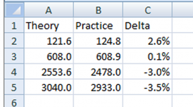
Modesty aside, I think that a possible prototype for such a table in Excel (could also be ported to OpenOffice) already exists. It evolved during my work with Quasimodo, and several evolutionary versions were presented in this thread over the last 12 months. The current version contains data for ten transformers, whereby one of them was also measured with the rectifier diodes connected.
This table provides also for automatically comparing the Rs value obtained for a particular transformer with the one obtained mathematically. All it needs is the natural (resonant) frequency entry in column E (obtained with Quasimodo) and, optionally, the secondary resistance in column D, in order to calculate the Rs value for the Zeta,opt value in column J. Of course, this is not obligatory; the table can be programmed not to do the check if the resonant frequency value in column E is absent. The check is currently there because I wanted to cross-check each experimentally obtained Rs value witrh the one coming from the formula.
So I'm putting this table as a possible prototype for consideration here.
Regards,
Braca
This is certainly an improvement over a non-updateable .pdf doc. It has (for me) far more data than I would be able to supply. But I'm not an engineer, sooo... 😱 I would also like to stick to the Quasimodo optimal zeta of 1.0 instead of .707 for reporting results - and yes, I know where the .707 came from but the 1.0 value is the accepted ideal here. Lastly, I'd want data from some "real world" equipment that's already in use; pre-amps, power amps, oscilloscopes - things we all use that seem likely to be compromised by ringing power supply secondaries. I would like to be able to use the collected info to go back and retrofit the proper snubber filters in these devices.
Perhaps we can report out findings here, and DNi/Braca can add it to his Excel file.
Again, just my $0.02, and worth every penny you paid for it.
Actually, it's much easier than you might think. You only need to enter three items in order to have the Excel sheet compute the theoretical value of Rs, these being the secondary winding resistance, the natural frequency (the oscillation you see on the scope with Rs removed from the Quasimodo ringer), and the Zeta value of your choice.
I already retrofitted my equipment with the appropriate CRC snubbers - no more capacitors across the rectifier diodes in my equipment!
Since the test I made with Quasimodo ringing a transformer connected to the rectifier and bulk capacitor showed only a small difference to the test with the transformer alone (see rows 9 and 10 in the table) you can, in principle, do your measurements on transformers within the equipment, but disconnect the mains first and check that the bulk capacitors are discharged! Also, you must know the details of the circuit in question in order to avoid measurement errors.
I'm now enclosing a version of the table in Excel format 2003. It might be of use to those who do not have Excel 2010.
Regards,
Braca
Attachments
I'm now enclosing a version of the table in Excel format 2003. It might be of use to those who do not have Excel 2010.
Regards,
Braca
Even better, as it opens in later versions of Excel just fine!

Need help with Quasimodo
I just assembled a Quasimodo (through hole version) and seem to be having a bit of trouble. The traces I get look nothing like what the documents indicate they should look like. (These are with a random transformer I had in my junk box).
The first photo shows the traces I get with RV1 uninstalled (=infinity) (the top trace is trigger and the bottom trace the normal scope output.
The next photo shows the traces I get with a random (virtually any value within the range of the trimpot).
If I remove C2 the trigger (at the drain of the MOSFET) is basically a perfect square wave.
So, not sure what I have done wrong. Any suggestions would be much appreciated.
Attachments


It appears you might be running your oscillator WAY too fast for this transformer. I suggest you fool around with different DIPswitch settings (there are only 2^4 = 16 of them) and find the setting which gives the largest period (the lowest frequency) measured at node DRAIN. It ought to be in the neighborhood of (frequency = 120Hz), (period = 8.3 milliseconds).
If yours is not ~ 120 Hz, you may have accidentally installed the wrong component values for the timing resistor R3 (39K) and/or the timing capacitor C4 (0.15uF). Or there may be a soldering error near those components.
If yours is not ~ 120 Hz, you may have accidentally installed the wrong component values for the timing resistor R3 (39K) and/or the timing capacitor C4 (0.15uF). Or there may be a soldering error near those components.
Thanks Mark for your quick reply. As I skimmed through all of the 600+ posts again I started to realize that I had not focused enough attention on the settings of the DIP switch. (it was late). I will check that out tonight.
Soldering errors? Me? 🙂 (that is always the first thing I check since I have been known to make a few). It seems to be a hazard, for me at least, of midnight engineering.
And kudos for coming up with such a clever idea and implementation as well as for your extreme patience in dealing with all of the questions. Your instruction has been very educational.
Mark,
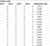
I checked last night and sure enough I had set the frequency incorrectly. I created this handy-dandy chart to remind myself not to do that again (these were actual measured, as opposed to calculated, frequencies).
Quasimodo is now working as expected.
Thanks again for your help.
I checked last night and sure enough I had set the frequency incorrectly. I created this handy-dandy chart to remind myself not to do that again (these were actual measured, as opposed to calculated, frequencies).
Quasimodo is now working as expected.
Thanks again for your help.
Attachments
I copied data for transformers with known part numbers to the Google spreadsheet and updated format to match DNi's spreadsheet closely.I'm now enclosing a version of the table in Excel format 2003. It might be of use to those who do not have Excel 2010.
Here is a link to a publicly editable Google Sheet for submissions
https://docs.google.com/spreadsheets/d/16LZJJDktNICWGBaKyiltrLlcUE_y0AGZYozTySv4dZ0/edit?usp=sharing
One does not need to use a Google ID to edit the above Google spreadsheet. The spreadsheet is setup to be publicly editable.They glean and mis-use more than enough of our personal information.
Last edited:
I wonder, is it really of any meaning to use snubbers for really low current circuits?
For example, if you have a full wave bridge supplying a DC circuit that draws 5-10mA, would a snubber be actually worth considering?
One would say that it will for sure improve matters, but who would care about such a subtle improvement?
Not playing devil's advocate here, just wondering whether to use a snubber on a tube bias circuit - and since I want to save some space, I was thinking about using a snubber on HT only. 🙄
... if you have a full wave bridge supplying a DC circuit that draws 5-10mA, would a snubber be actually worth considering?
The answer depends on the details of the transformer, the details of the rectifiers, the details of the filter capacitors, and the personal taste of the circuit designer.
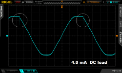
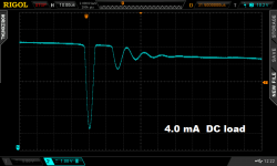
I have attached two oscilloscope photos that show the voltage across the transformer secondary, for one particular combination of (transformer, rectifiers, filter capacitors), with a 4.0 milliampere DC load.
Picture1 shows a full 60Hz AC cycle; the diode induced oscillatory ringing is circled in white. {Yes the power line waveform certainly does have a flat top in my neighborhood!} The transformer secondary voltage is ±12.5 volts, and the downward spike amplitude is 5 volts (!) with this tiny 4mA load.
Picture2 is a zoom-in of the ringing oscillation. The spike-down is so great that the subsequent half-cycle of oscillation rings upward high enough to actually turn on the rectifier diode again (!!), between t = 43usec and t = 53usec.
Is it "actually worth considering" a snubber for this power supply? Different designers will give different answers. My own personal answer is: yes I think it is worth considering a snubber for this power supply.
_
Attachments
It is known that very simple amplifier circuits tend to have poor PSRR (Power Supply Rejection Ratio), whereas more complicated amplifier circuits can be designed to have very high PSRR.
Thus, good PSRR amps will tolerate misbehaving PSU whereas poor PSRR amps will have poor performance with a misbehaving PSU.
Sort the PSU first. Then sort the amplifier. Then experiment with how bad the PSU can be made to perform to find out how well the amplifier tolerates a poor PSU.
Valve amplifiers running on HV B+ @ quite low current tend towards very simple amplifiers with very poor PSRR. That's why we see so many with CRCRCRC supplies.
Mark, were the diodes in that power supply particularly poor for reverse recovery, or a typical large current type diode with a typical reverse recovery ?
If the secondary was a single winding, with a 4-diode full bridge, then wouldn't a spike be expected on the opposite phase polarity?
Interesting waveforms to assess - top stuff.
If the secondary was a single winding, with a 4-diode full bridge, then wouldn't a spike be expected on the opposite phase polarity?
Interesting waveforms to assess - top stuff.
Consider it a challenge, see whether you can put together a transformer, rectifier(s), and filter capacitor(s), driving a DC load of 4mA, which produce a reverse recovery spike amplitude >40% (5 / 12.5) of the secondary voltage. Messages #44 and #45 in the Cheapomodo thread, indicate this is unlikely.
(An earlier post by user DNi) achieved a 21% spike amplitude (2.5 / 12) when his supply was delivering 50 mA DC to the load. It would have been even taller if he had used a different Cx.
(An earlier post by user DNi) achieved a 21% spike amplitude (2.5 / 12) when his supply was delivering 50 mA DC to the load. It would have been even taller if he had used a different Cx.
Hi,
I am planing to design some power boards and want to include placeholders for snubbers in SMD packages.
What are the appropriate SMD packages for Cx Cs Rs regarding expected values and disipation?
My boards will be relatively low power, 1-2 A current max.
Thanks in advance 🙂
I am planing to design some power boards and want to include placeholders for snubbers in SMD packages.
What are the appropriate SMD packages for Cx Cs Rs regarding expected values and disipation?
My boards will be relatively low power, 1-2 A current max.
Thanks in advance 🙂
Last edited:
Depends on what type of caps and resistors you want to use. Also, depending on that choice you will have to make compromises on smaller values. The answers you are looking for are a few clicks away in Mouser's advanced search.
OK, what is typical order of magnitude for Cx Cs Rs and what is typical power disipation of Cx Cs Rs?
When you begin your design work, I recommend you read the Quasimodo design note. It's attached to post#1 in this thread. The design note offers a recommended starting point for your design efforts, and discusses the calculations (or SPICE simulations) you'll need to do when estimating power dissipation ratings. Real world examples can be found throughout this thread, from happy and perhaps-not-so-happy people who built their own Quasimodo test-jig, and used it to design their own snubber, optimized for their own transformer.I am planing to design some power boards and want to include placeholders for snubbers in SMD packages.
- Home
- Amplifiers
- Power Supplies
- Simple, no-math transformer snubber using Quasimodo test-jig