Arrgh! Error there - that should read -0.023dB at 20KHz!
Showing signs of intoxication on a Sunday afternoon.
Cheers,
Greg😀
Showing signs of intoxication on a Sunday afternoon.
Cheers,
Greg😀

This previous test is done without need for an output RL parallel network.
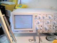
A clearer pic of the module is now displayed on my website
Cheers,
Greg
A clearer pic of the module is now displayed on my website
Cheers,
Greg
AndrewT said:Hi,
BUT these same contributors repeatedly criticise other topologies saying they have each done it better but are not prepared to show us how to do it better. I would much prefer that you shut up or put up. but there is a limit to how many times some repeat themselves "I've done it better".
Hi Andrew T ,
Dont get so much upset, I and Guru haven't criticised anybody's design so far on this forum, yes but pointed out the short comings in some designs as well........
Stay Cool.....because everybody needs your assistance on this forum...me too!
K a n w a r 😉
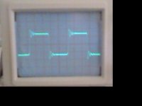
amplifierguru said:Oh and here's the sq wave into 8 ohms at 10KHz. The rolloff is as expected from the 1K and 1000p (polystyrene) input filter at 160KHz delivering -0.6dB at 20KHz and providing substantial filtering of stray hf pickup.
Nice wave, no overshoot, but what's the amplitude? Looks like 'not very high' slew values.
Hi Darkfenriz,
Yes, you're right these were done at 10Wrms - about the average power on music of a 150W amplifier with peaks near clipping.
I will do some higher power tests as soon as I increase my dummy load size from 25Wrms and hopefully improve camera resolution.
Cheers,
Greg
Yes, you're right these were done at 10Wrms - about the average power on music of a 150W amplifier with peaks near clipping.
I will do some higher power tests as soon as I increase my dummy load size from 25Wrms and hopefully improve camera resolution.
Cheers,
Greg
Originally posted by mastertech
"Oh and Mikeks here it is again, just in case you can't find it -
cheers"
Mikeks "Where...?"
Mike my good friend the above is not my quote it is ampguru's
btw i havent seen a schematic of yours since ive been to this
forum is there any chance we would see one
there is no reason to feel shy if you make mistakes such as this
one. chill out man! shows a schematic of yours,
regards
"....10KHz square wave when loaded with 8ohms and 2uF...."
I am curious about the square wave behaviour with 8 ohms and lower capacitance loads like 0.1uF , 0.22uF and 0.47uF .
Have you tried that .....with and without the Zobel network ?
Cheers.
I am curious about the square wave behaviour with 8 ohms and lower capacitance loads like 0.1uF , 0.22uF and 0.47uF .
Have you tried that .....with and without the Zobel network ?
Cheers.
Hi Mastertech,
It's not just me then - this Mikeks seems short on detail and ever-present on snipe, with zero contribution. Chill seems fair!
Hi ashok,
Yes I usually start with small values like 0.1uF (which I did to no visible effect) and up. 2uF is a bit of a standard so I jumped to that but have since tried 0.22uF with no effect. In time.
I have an RC to ground just to define the impedance at HF but no R//L isolation. Good if it's not necessary - but I really won't know until I've put it through every practical test.
Cheers,
greg
Hi ampguru
i see you are a user of dodo internet
a question off subject , the dialup number 0198 307 137
is listed on their site as dialup for all states
i want to find out if it is a local call one for all states
do you know what states it is a local call one
what state are you, are you using this number
you could email me with an answear at g3000@dodo.com.au
just want to make sure it is a local call one
your help would be appreciated
regards
Mikeks always has a shortage of words...Why???
Do these words cost him huge fortunes or This is his inherent Style of posting in its own uniqueness.....
OH Mikeks PLease tell us........Whaaayy....Whaaaayyyy.... but i love to see you cry........😀 😀 😀
Kindly give us answer in 5 words atleast.....
I think forum members are waiting to see your heavy word loaded postings...
K a n w a r
open-loop gain?
Seems to me that this topology requires fairly high gain to drive the damping factor/output impedance down. So assuming rout looking into the pmos/nmos is 10kohms each (very likely to be higher), the output resistance open-loop will be 2.5kohms.
Let's then assume a damping factor of 10 for an 8ohm load. This requires the feedback to be in access of 3000 (~70db) to hit a 0.8ohm output resistance closed-loop.
Greg, so how did you achieve a damping factor >1000 ? and what is the overall gain? I must be missing something......
Thanks,
Richard
here's the sq wave into 8 ohms at 10KHz
these were done at 10Wrms
Greg, is this slew rate limiting caused by insufficient current to output MOSFET gate through EF emitter resistors?
Richard,
Yes, you are right, without feedback the amp is voltage-controlled current source. Assume the overall transconductance G1 is 10000A/V, with 8Ohm load (R1) the gain would be 80000. The closed loop gain is R2/R3=44, so the loop gain is 1800. The voltage source in series with load represents the back emf. The rejection of this voltage on the output (node 1) is equal to inverse loop gain, so DF=1800
Yes, you are right, without feedback the amp is voltage-controlled current source. Assume the overall transconductance G1 is 10000A/V, with 8Ohm load (R1) the gain would be 80000. The closed loop gain is R2/R3=44, so the loop gain is 1800. The voltage source in series with load represents the back emf. The rejection of this voltage on the output (node 1) is equal to inverse loop gain, so DF=1800
Attachments
Dimitri,
It's hard for me to reconcile your diagram of an ideal current source with the definition of damping factor. My understanding of damping factor is merely the ratio of the load impedance vs the output impedance of the amp. Your diagram shows an ideal current source output with infinite impedance. So what is the output impedance after closing the loop? Infinity divided by loop gain = ?
It's hard for me to reconcile your diagram of an ideal current source with the definition of damping factor. My understanding of damping factor is merely the ratio of the load impedance vs the output impedance of the amp. Your diagram shows an ideal current source output with infinite impedance. So what is the output impedance after closing the loop? Infinity divided by loop gain = ?
rlim
You should take open loop impedance parrallel with load impedance and divide by loop gain. Your approximation calculation is true for amplifiers with relatively high OL damping factor, say >5. In transconductance amps DF=~ loop gain, infinity parallel with 8Ohms is 8 Ohms.
You should take open loop impedance parrallel with load impedance and divide by loop gain. Your approximation calculation is true for amplifiers with relatively high OL damping factor, say >5. In transconductance amps DF=~ loop gain, infinity parallel with 8Ohms is 8 Ohms.
amplifierguru said:I will do some higher power tests as soon as I increase my dummy load size from 25Wrms and hopefully improve camera resolution.
Greg,
if you dunk your dummy load resistor into a bucketfull of water, it will increase its power rating tenfold. If your water is as in most of Oz (rain water), tap water will be OK. If it is too conductive, use distilled water.
As far as camera improvement, I'd suggest a nice DSLR with 6 megapixels or more 🙂
Cheers,
Bratislav
Bratislav,
This is very bad advice - water has very high transconductance, and will overload the amp..........
And besides, for any kind of thermal capacity, it should be heavy water!!
Hugh
This is very bad advice - water has very high transconductance, and will overload the amp..........
And besides, for any kind of thermal capacity, it should be heavy water!!
Hugh
darkfenriz:
Not true. Transconductance amps typically have low damping factors due to high output impedance, unless you have extremely high loop gain.
In transconductance amps DF=~ loop gain, infinity parallel with 8Ohms is 8 Ohms.
Not true. Transconductance amps typically have low damping factors due to high output impedance, unless you have extremely high loop gain.
- Status
- Not open for further replies.
- Home
- Amplifiers
- Solid State
- Simple Killer Amp!