Thanks Bratislav. I did the water thing with my old dummy load and water ingress over time, I'm sure, contributed to it's demise. But the thought of a cup of tea after protracted power testing seemed like a good idea at the time). All fixed.
Hi rlim,
..."Transconductance amps typically have low damping factors due to high output impedance, unless you have extremely high loop gain."
And that's exactly what the Simple Killer Amp has!
Try 80dB in the bootstrapped first stage and 30dB in the output stage with a two pole response from 100KHz due to the output stage and a feedback zero to compensate.
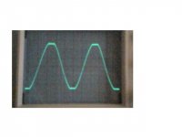
By the way, I've been doing some power tests . Here's absolutely clean clipping at +/- 52V into 8 ohms -
-
Hi rlim,
..."Transconductance amps typically have low damping factors due to high output impedance, unless you have extremely high loop gain."
And that's exactly what the Simple Killer Amp has!
Try 80dB in the bootstrapped first stage and 30dB in the output stage with a two pole response from 100KHz due to the output stage and a feedback zero to compensate.
By the way, I've been doing some power tests . Here's absolutely clean clipping at +/- 52V into 8 ohms
-Attachments
amplifierguru:
Wow! 80db in the bjt stage! Hard to believe the self-gain of a bjt can be that high.
Interesting circuit you have there. Regardless of how high the gain is, and how low the damping factor is in a transconductance amp, there is still no clear consensus what sounds good, one way or the other. Just makes me wonder what the audiophile's preference is if one were to lower the 1st stage gain to, say, 40db, or even 20db(hello jfets) with a corresponding increase in damping factor.
Thanks for showing us this neat circuit.
Richard
Try 80dB in the bootstrapped first stage and 30dB in the output stage with a two pole response from 100KHz due to the output stage and a feedback zero to compensate.
Wow! 80db in the bjt stage! Hard to believe the self-gain of a bjt can be that high.
Interesting circuit you have there. Regardless of how high the gain is, and how low the damping factor is in a transconductance amp, there is still no clear consensus what sounds good, one way or the other. Just makes me wonder what the audiophile's preference is if one were to lower the 1st stage gain to, say, 40db, or even 20db(hello jfets) with a corresponding increase in damping factor.
Thanks for showing us this neat circuit.
Richard
AKSA said:Bratislav,
This is very bad advice - water has very high transconductance, and will overload the amp..........
And besides, for any kind of thermal capacity, it should be heavy water!!
Hugh
Hi Hugh,
I wasn't joking. I used water cooling during high power testing of my Krell clone (> 1kW into approx 1 ohm, roughly 50A peak).
Water has very high dielectric constant (80, compared with glass which is less than 10, and most would agree glass is pretty good insulator ! "Standard" insulators like PVC and teflon have d.c. of less than 3).
As far as heavy water, well a bucket of water will take a few KW for many minutes before boil, and then keep the resistor at safe 100 degrees until all of water evaporates.
By then your output stage would be well and trully melted !

Bratislav
PS in my case it were 2 ohm emiter resistors that smoked out a bit and tuned brownish, but survived. (I've replaced them anyway). Transistors, being 8 pairs of 20A TO3 devices were positively unfazed.
Hi rlim,
Thanks. One of the options which is detailed in the kit assembly instructions is to try it with the bootstrap C's removed! This drops the first stage gain by 40dB and increases (closed loop) low order THD from 0.005% to 0.25-0.3% for more 'bloom'. As you point out, it will decrease DF as well. Very tube like?
Hi Dimitri,
Those 10KHz square waves were not slew rate limited at all, only bandwidth limited (rolloff) due to the 1K//1nF input filter - and are exactly as expected.
Bratislav,
I always used demineralised water I had for the car radiator.
Cheers,
Greg
Hi Greg,
will we see some measurements of the harmonic spectrum in the future, perhaps both with and without that Bootstrap Cap, it would be interesting! 🙂
Cheers Michael
will we see some measurements of the harmonic spectrum in the future, perhaps both with and without that Bootstrap Cap, it would be interesting! 🙂
Cheers Michael
Hi Amp Guru,
can you post a pic of the 10kHz and/or 20kHz injected after the RF input filter?
Your RF filter is set quite low. Can we have your thoughts on why you chose this RC time constant rather than 0.75uSec to 0.3uSec?
can you post a pic of the 10kHz and/or 20kHz injected after the RF input filter?
Your RF filter is set quite low. Can we have your thoughts on why you chose this RC time constant rather than 0.75uSec to 0.3uSec?
Hi Bratislav,
Yes, I agree and also have experience with this cooling method. I built a 60W SE hybrid amp some years ago, it's baby brother is here:
http://www.aksaonline.com/discussion/discussion_papers_project.html
About ten years ago I did a 1.2Kw amp, using a coiled wire load on ceramic, and for over eight hours it ran red hot - a friend lit his cigarettes on it!
Presently I'm working on a balanced, choke loaded tube/mosfet hybrid which uses forced air cooling. This dissipates around 120 watts per channel from two heatsinks and a 120x120 fan.
Cheers,
Hugh
Those 10KHz square waves were not slew rate limited at all, only bandwidth limited (rolloff) due to the 1K//1nF input filter - and are exactly as expected.
But the picture with performance with capacitive load looks like it could be a slew rate limited😉
slew rate limited
This is a not an abnormal picture in my view for this kind of load.
Also the picture is not so sharp to conclude the amp is slewrate limited.
Interesting amplifier so far, let us give the Guru time to finish the prototype.
greetings, Loek
This is a not an abnormal picture in my view for this kind of load.
Also the picture is not so sharp to conclude the amp is slewrate limited.
Interesting amplifier so far, let us give the Guru time to finish the prototype.
greetings, Loek
Hi Michael,
Yes I will do THD or FFT with and without the bootstrap C's. Interesting that, since they don't change the DC conditions at all, they can just be there or not, with such an interesting variation.
Hi Andrew T,
I believe in fairly steep input filtering and never have any interference/stray pickup. A hangover from my early PA days where anything out of band was better suppressed. But a 160KHz (or 250KHz option) filter causes less than 6 degrees phase shift at 20KHz and less than 2 degrees non linear. Neg!
Hi Jarek,
Not at all. Not the best picture quality sadly but you would see quite the opposite that the ringing waveform is faster in the rise and fall than the input - due to the overshoots.
Thanks Loek,
In fact the amp is finished and I haven't changed a thing from the 2 prototypes playing in my lounge room. I've had some test equipment problems that had me worried for a while. Had to rebuild a sig gen after spurious output.
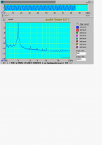
Here's a FFT at 12.5W a convenient level as it equals my soundcard max with the feedback divider i.e. max loopback.
Cheers,
Greg
😉
Yes I will do THD or FFT with and without the bootstrap C's. Interesting that, since they don't change the DC conditions at all, they can just be there or not, with such an interesting variation.
Hi Andrew T,
I believe in fairly steep input filtering and never have any interference/stray pickup. A hangover from my early PA days where anything out of band was better suppressed. But a 160KHz (or 250KHz option) filter causes less than 6 degrees phase shift at 20KHz and less than 2 degrees non linear. Neg!
Hi Jarek,
Not at all. Not the best picture quality sadly but you would see quite the opposite that the ringing waveform is faster in the rise and fall than the input - due to the overshoots.
Thanks Loek,
In fact the amp is finished and I haven't changed a thing from the 2 prototypes playing in my lounge room. I've had some test equipment problems that had me worried for a while. Had to rebuild a sig gen after spurious output.
Here's a FFT at 12.5W a convenient level as it equals my soundcard max with the feedback divider i.e. max loopback.
Cheers,
Greg
😉
Attachments
Hi, Amplifierguru,
Where can I see a picture of you? I've seen Mr. Dean and his beautiful (not joking 😀) family.
Where can I see a picture of you? I've seen Mr. Dean and his beautiful (not joking 😀) family.
amplifierguru said:
Here's a FFT at 12.5W a convenient level as it equals my soundcard max with the feedback divider i.e. max loopback.
😉
Hello, Guru
My paper amp is cleaner - nothing for the first 120dB!
😀 😀 😀 😀
Cheers,
that the ringing waveform is faster in the rise and fall than the input - due to the overshoots.
But just a little only🙂
The frequency of ringing is rather small, I think a hundreds of kHz max.🙂
Hi Lumanauw,
I don't want to bore people on the forum with family pics, but I'll send you one by email. I'll show you mine if you show me yours.
Hi Jorge,
That's good for you. Aren't paper amps great. However, the intention with the Simple Killer Amp was never to produce vanishing THD of -120dB, it was intended as a standalone simple amplifier which made efficient use of the power supplies while having the speed of MOSFETs in a unique topology using only small signal BJTs but with considerably better PSRR than the conventional Vas/EF.
It has achieved all it set out to do and contrary to popular belief, is not unstable nor poor in current sharing. In fact it has proved to be one of the most stable amplifiers I have ever built, the thermal tracking is spot on and THD is reasonable and better than many Hi End offerings. THD is below 0.005% at average power and predominantly second harmonic, rising at high power to just over 0.01% at 100W composed of 2nd and 3rd with all other artefacts below at or below -90dB (see pic).
Primarily it was intended as an experimenters amplifier - one that could be operated in Class AB or Class A, AC coupled or DC coupled, and with or without bootstrap C's for more or less 'bloom' and Damping Factor. One simple compact PCB.
In this respect it's unique, educational and rewarding. I am confident of it's suitability as a full range, sub-amp or band limited unit for bass/mid/treble.
If, however, one is chasing disappearing THD of -120dB the whole amplifier can be easily driven from a suitable quality chip op-amp in a nested loop, with few peers.
Hi Jarek,
.................and.......?
Cheers,
Greg 😀
Attachments

Hi, Amplifierguru,
I also don't want to load this site with pictures. But I always wonder what an audio power amp designer looks like 😀
You can see a picture of me in www.rocket-audio.com
Back to technical.
Is it possible to make this killer design an X amp? Like this one http://www.diyaudio.com/forums/attachment.php?s=&postid=732896&stamp=1127896282
I think with X operation, it will boost PSRR even more.
To quote an old writer here:
ini apa toean Lumanauw datang.
Great looking car amplifier, great looking website, Toean Lumanauw.
Nice to see a name AND a face.
ini apa toean Lumanauw datang.
Great looking car amplifier, great looking website, Toean Lumanauw.
Nice to see a name AND a face.
Hi Lumunauw,
Yes it's possible to do a balanced input, bridge output Killer Amp. And yes PSRR is further aided, as the artefacts appear equally on both outputs.
The output stage is ideal for your application with the lowest losses especially with low voltage p channels which have lower losses than the > 100V ones I'm using.
Me at the beach cropped from a family shot (note the Zn cream on nose) -
Cheers,
Greg
Attachments

Some further results following on the 100W FFT post. As you're probably aware I was running the output MOSFETs at 50mA each.
Also my test jig has the PS wired to the module with about 200mm of 24/0.2 for V+,V-,PG.
So I decided to investigate the effect of shortening the PS wiring on the (particularly) even harmonic distortion. Shortening to 75mm had no visible effect on FFT residuals indicating to me that PSRR is good and the amp shouldn't be overly sensitive for it's performance to supply impedance.
Then I doubled the MOSFET standing current to 100mA per device (24W c.f. 12W). This visibly reduced the odd orders by maybe 3dB. However the improvement is arguable over the 50mA bias as 2/3 and 4/5 etc were approximately equal. So it's optimised.
Cheers,
Greg
Attachments

- Status
- Not open for further replies.
- Home
- Amplifiers
- Solid State
- Simple Killer Amp!