Hi Jorge,
I'll look into the email forwarding. The email link on DIY should get me.
Hi CBS240,
BJTs have a -ve tempco at about -2mV /degC i.e. they go on harder if not tracked. Same applies for these MOSFETs but at roughly -5mV/degC - but in a Vgs of some 6 times the Vbe of a BJT so overall about half the % change of a BJT.
Class B - the only reason I would run Class B is when I couldn't hold the bias on the AB stable. It would be a desperate measure as it creates a discontinuity in the forward path and the NFB can't function creating a dead zone of high distortion, very unpleasant but doesn't read high on a THD meter. In this new amplifier each MOSFET is biassed at roughly 45mA so quiescent dissipation is about 10W for 2 pair.
I've just received my boards and am populating the first for webpics. Checking for board problems.
Cheers,
Greg
Hi Cbs,
vertical power FETs (switching type) change from negative to positive temp coeficient at about 4A to 8A in the datasheets I have seen. So they will probably have overheated before the positive coeff gets a chance to help you out.
Lateral power FETs seem to change from positive to negative between 100mA and 500mA on my datsheets (1058, 160, 80, 225, 50, 135 etc) so if you bias at about this level they are effectively positive at or soon after the current starts rising. This way they get a chance to protect themselves without needing a thermal compensator. They still need adequate heatsinking but can run hotter than BJTs in emergencies since they don't have secondary breakdown.
It is possible that pairs of lateral FETs may not need source resistors to balance their Iq but three or more will require source resistors. Vertical FETs always require source resistors as well as much higher bias voltage.
Hi Andrew T,
..."Vertical FETs always require source resistors as well as much higher bias voltage."...
I suppose IRF hexfets qualify as verticals in which case I draw your attention to my topology where, in practice, neither are true! The MOSFET's are however matched to 10mV (in avg 3.5V or .3%) and have an internal Rs that increases with temp. Also, the higher Vgs (about 5.5V at 4A) is not a factor as they are operated in common source mode where Vgs is not a loss.
In effect, I've eliminated both these shortcomings leading to a higher possible output power or lower supply voltage. Thus the amplifier makes very efficient use of the supplyrails and I have a 50W Class A version that runs from +/- 32V and dissipates only 115W! Or 100W Class AB easily running from +/- 45V supplies.
Cheers,
Greg
AndrewT said:Hi Amp Guru & Workhorse,
Now that you are talking to each other maybe you can exchange schematics showing each of your solutions to the problems that you claim to have overcome.
You certainly do not seem to want to show them to the rest of us.
Hello Andrew T ,
The commercial designs are our bread & butter & life ofcourse, therefore I couldnot show you guys our commercial products design...kindly understand the gravity of situation......
The Reason: I have spent 3 years on Research and Development of NVMOS amp which is an exceptional design , if compared with other designs in terms of performance, sonics, simplicity, ergonomics, reliability...
Though Some details:
Small Signal Transistors 2N5401/5551 + MJE350/340 are only used BJT's in my circuit....
Mosfets are From IRF = IRFP260 in 1600W & 2400W designs and from APT as well = APT30M18LVR in 3600W designs.......
Rail Voltage = + - 75VDC[1.6K] , + - 95VDC[2.4K] , + - 130VDC[3.6K]
Rail Loss = 1 volt max...in worst case condition during 2 ohms load
Input Stage = Differential -> Emitter Follower driving Cascode Pair -> Thermal Tracking ->Active Turn-off assisted driver stage....
No - VI limiting, except Overcurrent[I drain] is limited by Zeners at Gate to source terminals of individual Mosfets
Short circuit protection activates when current through all collective mosfets is around 1 to 2 amperes and output voltage is Zero...thus positively safeguards the output stage from Dead Shorts in less than 50mS..
PS: In traditional S C Protection the activation takes place only when the current through the all collective Devices increases above the specified limit in range of 10A to 30 A in most pro amps, In our case if there is a short circuit , then the detection takes place when the current reaches above 1 ampere threshold AND output voltage is Zero, thus relifs the output stage from conducting currents in excess of 2 amps which is i think a safe criterion...
regards,
K a n w a r
Aren't hexfets generally more non-linear? as if a transistor could actually be linear anyway🙄 Guess that's why we come up with crazy error correction schems...
Hi CBS240,
Yes, bit rhetorical, but I'm less concerned with small difference in linearity between types as you would need to weigh all the other characteristics to come to any conclusion as to the most suitable device for a particular application. In reality non-linearity (within reason) is well dealt with by NFB either globally, locally or both as long as the forward path doesn't have discontinuities as in Class B or underbiassed AB - perhaps as a result of too effective Tcomp.
Cheers,
Greg
amplifierguru said:A prime example is Douglas Self's series, where, with all the machinations, the single biggest improvement came when he tried a regulated PS - the distortion dropping from > 0.03% to 0.006% -Cheers,
Greg
Total misrepresentation of Self's work....totaly untrue...
🙄
Hi Mikeks,
Come up with that 40dB RC filtering of the diff'l/Vas yet? Didn't think so?
Sniping again - better get out your Dougie Self 'bible' and read it for yourself! I'd hazard a guess that all his low THD tests were done with reg supplies, but there's nothing definitive to confirm either way. As I've said before, without attention to PSRR in the std Vas topology you're listening to PS artefacts.
Sad but true and all the sniping isn't going to change the fact.
Cheers,
Greg
Hi amplifierguru,
Maaate, are we talking about Douglas Self's "Audio Power Amplifier Design Handbook". In this text he is generally talking about unregulated power supplies. (Obviously, excluding the sections on regulated and switching power supplies).
Regards 🙂
Maaate, are we talking about Douglas Self's "Audio Power Amplifier Design Handbook". In this text he is generally talking about unregulated power supplies. (Obviously, excluding the sections on regulated and switching power supplies).
Regards 🙂
Re: PSRR
http://www.diyaudio.com/forums/showthread.php?postid=627086#post627086
Should be closed loop...
amplifierguru said:Hi Mikeks,
Come up with that 40dB RC filtering of the diff'l/Vas yet? Didn't think so?
http://www.diyaudio.com/forums/showthread.php?postid=627086#post627086
Jorge said:Just to make it clear - are we talking about open loop or closed loop PSRR?
Should be closed loop...
Greg Erskine said:Hi amplifierguru,
Maaate, are we talking about Douglas Self's "Audio Power Amplifier Design Handbook". In this text he is generally talking about unregulated power supplies. (Obviously, excluding the sections on regulated and switching power supplies).
Regards 🙂
True!!!

Which is why i suspect 'amplifierguru' is making comments about material he hasn't read... 🙄
Workhorse said:
THE BJT:
......yields low slew rate...
No
It suffers from High VCES[saturation voltage] upto 2-3 volts, which hampers it from deliverig rail to rail swings.
No
Much better than MOSFETs in this respect...
It yields less damping than Mosfets at a given impendance..
No
K a n w a r
mastertech said:Oh and Mikeks here it is again, just in case you can't find it -
cheers
Where...?
Mike,
You mentioned your design that has a good PSRR, any chance of enlightening us with a schematic ..............😉
Regards,
Jam
You mentioned your design that has a good PSRR, any chance of enlightening us with a schematic ..............😉
Regards,
Jam
You mentioned your design that has a good PSRR, any chance of enlightening us with a schematic ..............
Yes, Mikeks, why don't you give a schematic (without values is OK), for learning purpose only, not for hijacking your commercial units 😀
Hi,
many of us are here to learn and sometimes pass on our knowledge to others so that all may benefit.
Some of our contributors are obviously from a commercial background and very knowledgable. For commercial reasons they are not prepared to divulge their trade secrets. That is their right. I support that right to the end.
BUT these same contributors repeatedly criticise other topologies saying they have each done it better but are not prepared to show us how to do it better. I would much prefer that you shut up or put up. Simply telling us that a better solution is available is NOT good enough. I would like to see constructive criticism here on the forum whether from experts, good amateurs, and not so good amateurs. All views and contributions are always welcome, but there is a limit to how many times some repeat themselves "I've done it better".
damping factor
Greg,
What are your thoughts on damping factor of your amp? Doesn't seem like the output impedance is that high.....
Thanks,
Richard
Greg,
What are your thoughts on damping factor of your amp? Doesn't seem like the output impedance is that high.....
Thanks,
Richard
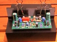
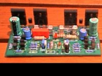
Whoops,
That was it clipped onto my test heatsink. Here's the one showing the thermal sensing BJTs.
Isn't that the best place? Reduces the thermal lag! They regulate the input stage current sources which control the bias current for the output stage.
Cheers,
Greg
That was it clipped onto my test heatsink. Here's the one showing the thermal sensing BJTs.
Isn't that the best place? Reduces the thermal lag! They regulate the input stage current sources which control the bias current for the output stage.
Cheers,
Greg
Attachments
- Status
- Not open for further replies.
- Home
- Amplifiers
- Solid State
- Simple Killer Amp!