Circuit sim 9V
I had another look at the Falstad simulator applet. I understand the working of the simple transistor amplifier - I built one after all (capacitors and all) - but the common ended amplifier had me mystified for a while. Specifically I did not understand the function of the resistors in the circuit except for the bias resistor.
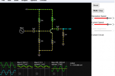
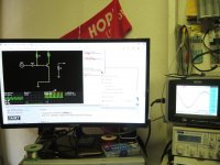
I found the fluid analogy in the simulator useful: the little yellow dots represent current. If I reduce the current source from 20V to 9V then less current will flow. To maintain the same current through the resistors, I would have to change the resistors, both of them. The current from the 9V source flows through the resistors and is diverted into two channels - and constricted by the resistors, which are like narrowing of pipes in fluid circuit. The waveform turned out the same shape as before, and I added some oscilloscope probes to check the voltage at some points on the circuit.
Two more resistors to go, and also find a way to obtain the same voltage swings at the output.
I had another look at the Falstad simulator applet. I understand the working of the simple transistor amplifier - I built one after all (capacitors and all) - but the common ended amplifier had me mystified for a while. Specifically I did not understand the function of the resistors in the circuit except for the bias resistor.
I found the fluid analogy in the simulator useful: the little yellow dots represent current. If I reduce the current source from 20V to 9V then less current will flow. To maintain the same current through the resistors, I would have to change the resistors, both of them. The current from the 9V source flows through the resistors and is diverted into two channels - and constricted by the resistors, which are like narrowing of pipes in fluid circuit. The waveform turned out the same shape as before, and I added some oscilloscope probes to check the voltage at some points on the circuit.
Two more resistors to go, and also find a way to obtain the same voltage swings at the output.
Attachments
Some questions I have asked in another thread:
Thanks. My next set of questions are about the class A amplifier I am trying to build. I started with a simple class A circuit with one bias resistor and the speaker in series with the transistor. Since it was not good to have DC currents go through the speaker I used a transformer, but this set up is not satisfactory.
Looking up other audio circuits like the ones in John Audio Tech on You Tube, and the circuit in the Falstad Circuit simulator, I see a set of four resistors in the Common-Emitter circuit. I understand the circuit except for the two 'bottom' resistors.
When the current comes into the circuit, it splits into two parts, with the higher current going through the lower resistance. The top left hand resistor controls the flow of current, essentially taps the current from the current source and sends a little of it to the base of the transistor to push the transistor into operating levels as a small current is required to do this.
The top right hand resistor limits the current through the transistor, since when fully open current will flow unimpeded through the transistor and the wires, causing it to get very hot,essentially a short circuit.
The top right hand resistor is sometimes called a current source, with a large 10W ceramic resistor used : I understand this acts a current reservoir of some sort, is this correct and is ti largely due to the inductance of wire wound resistors, or simply resistance? How does a change in a downstream resistance in this case cause a less than proportional increase in current through the resistor?
I have uploaded the Falstad circuit diagram screenshot for reference. I changed the supply to 9V and the top resistors accordingly to preserve the same current.
Two more questions: A resistor is like restriction in a hosepipe, so squeezing the tune creates restriction to the flow.
Now imagine the bottom left resistor is a section of tube on a hydraulic circuit that can be squeezed. Squeezing the bottom left resistor will cause a restriction of flow in the entire tube, that is the entire wire from top to bottom. This causes more current to be diverted into the base of the transistor. But why place a resistor here? Why not simply decrease the resistance of the top left resistor?
Also the bottom right resistor - the same could be said, why the second resistor. I read it is for thermal stability, ok, by restricting the amplitude of the output using a resistor here, does it reduce the amplitude change due to thermal effects, is that how it works? Is there another reason for this resistor?
BasicHiFi1: you need to know what a potential divider does, and that a bipolar transistor is primarily controlled by the base to emitter voltage.
Let's start at the beginning. What do two resistors across a supply line do assuming that nothing else is connected? No I can't wait for your answer- it's like watching a snail race.
It's a voltage divider. So the voltage at the junction between the two resistors is a ratio of the two resistance R2/(R1+R2) times the supply voltage. (R1 being your "top" and R2 your "bottom" resistors).
Now hook a bipolar base up to that. You've just set the base voltage of the transistor, assuming it takes a low current compared to the current flowing in the resistors.
What have you been told/learned about the base-emitter voltage of a transistor?
It's about 0.6 to 0.7V. Once the base voltage is set the emitter will want to "follow" it at 0.6 or 0.7V or thereabouts below it. You use that information to set the emitter current.
One caveat: that base voltage needs to be at least 0.6 to 0.7V higher than the emitter voltage you want.
Now you check that things are looking about right by estimating the base current and ensuring that it is less than at least a fifth of the current flowing in R1+R2. Then the circuit will bias close to what you want.
That emitter resistor provides some degree of negative feedback and thermal stability as a result. It's not perfect but miles better than having nothing unless there is a sense resistor in the collector.
Now, last point, you can set the collector resistor value. You've been told (several times) that the collector needs to sit at about half the supply voltage, or better, half the voltage difference between the supply rail and emitter voltage.
You know the current as you just set that with the emitter resistor (and base voltage, which sets the emitter voltage, approximately), and noting that the collector current is almost identical to the emitter current.
You know the voltage you need to drop across it now.
So Ohm's law again.
Please see if you can follow this before commenting again.
Last edited:

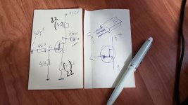


See my post #23. That includes a CCS transistor.
Resistor R3 needs to be adjustable. Best operated with a current driven input.
Resistor R3 needs to be adjustable. Best operated with a current driven input.
Resnick Halliday Walker Fundamental of PhysicsThat's a lot of information. I will read and re-read those posts. Can anyone suggest a suitable Physics textbook?
BasicHiFi1: you need to know what a potential divider does, and that a bipolar transistor is primarily controlled by the base to emitter voltage.
OK
Let's start at the beginning. What do two resistors across a supply line do assuming that nothing else is connected? No I can't wait for your answer- it's like watching a snail race.
It's a voltage divider. So the voltage at the junction between the two resistors is a ratio of the two resistance R2/(R1+R2) times the supply voltage. (R1 being your "top" and R2 your "bottom" resistors).
So the resistors 'drop' the voltage across each. Each additional resistor reduces the current in the entire circuit.
Now hook a bipolar base up to that. You've just set the base voltage of the transistor, assuming it takes a low current compared to the current flowing in the resistors.
What have you been told/learned about the base-emitter voltage of a transistor?
It's about 0.6 to 0.7V. Once the base voltage is set the emitter will want to "follow" it at 0.6 or 0.7V or thereabouts below it. You use that information to set the emitter current.
One caveat: that base voltage needs to be at least 0.6 to 0.7V higher than the emitter voltage you want.
OK
Now you check that things are looking about right by estimating the base current and ensuring that it is less than at least a fifth of the current flowing in R1+R2. Then the circuit will bias close to what you want.
The Falstad sim shows the following for the standard Common-Emitter Amplifier circuit, 20V without modification: Current in 110k resistor = 177 uA, 10k resistor 110 uA, base current Ib is listed as 5.2 uA
That emitter resistor provides some degree of negative feedback and thermal stability as a result. It's not perfect but miles better than having nothing unless there is a sense resistor in the collector.
I do not understand negative feedback. In my understanding negative feedback consists in sending an 180 degree out of phase signal into the base.
Now, last point, you can set the collector resistor value. You've been told (several times) that the collector needs to sit at about half the supply voltage, or better, half the voltage difference between the supply rail and emitter voltage.
The collector resistor, ok the top right hand one. Any resistor creates a 'voltage drop', so in the Falstad, the voltage across the resistor is 14V. A scope across the resistor shows a max of 14V across the resistor.
You know the current as you just set that with the emitter resistor (and base voltage, which sets the emitter voltage, approximately), and noting that the collector current is almost identical to the emitter current.
Collector current and emitter current 1.432 mA and 1.451 mA respectively.
You know the voltage you need to drop across it now.
So Ohm's law again.
Please see if you can follow this before commenting again.
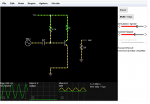
I have got my original "YouTube" circuit working and on Falstad so I can add components and see what happens.
Set up in simulator
My original amplifier lets call it November 1, is set up in the simulator. I will check the actual component values and change it if necessary. Here it is. The first thing is to move the speaker 8 Ohm load out of the supply voltage - collector line and connect it across the collector and ground.
My original amplifier lets call it November 1, is set up in the simulator. I will check the actual component values and change it if necessary. Here it is. The first thing is to move the speaker 8 Ohm load out of the supply voltage - collector line and connect it across the collector and ground.
Attachments
OLDIY your diagram is a real clear solution. I probably need to do this. The second potentiometer is a gain control. The resistor across the speaker is to reduce hum and distortion?
Few days back I put this together. Meant as headphone amp, but it can drive bookshelf to moderate spl. Sounds really good, only second harmonic. It uses power jfet lu1014d.
Thanks. Need to source the jfet.
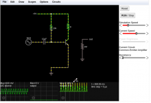
Circuit in Circuit Sim, actual components
Actual components used:
1) 50V 10 uF non polarized capacitor
2) Resistor - -Brown- Black -Orange - Gold - 10k Ohm
3) Transistor - TIP 41A
The simulator plot taken across the 8 Ohm resistor, representing the speaker, is pretty ..... awful.
Sorry Vincent...
Actual components used:
1) 50V 10 uF non polarized capacitor
2) Resistor - -Brown- Black -Orange - Gold - 10k Ohm
3) Transistor - TIP 41A
The simulator plot taken across the 8 Ohm resistor, representing the speaker, is pretty ..... awful.
Now I understand
What you tried to say to me
And how you suffered for your sanity
Sorry Vincent...
Attachments
Last edited:
+ 1000 🙂Resnick Halliday Walker Fundamental of Physics
That was my Physics Textbook when I started studying Engineering in 1969 , hesitated suggesting it here because didn´t think it was popular "outside" , although it was published by one of the great Science publishing houses: Wiley & Sons, but now I googled it out of curiosity and found high praise for it (which is well deserved):
Fundamentals of Physics is a calculus-based physics textbook by David Halliday, Robert Resnick, and Jearl Walker. The textbook is currently in its eleventh edition (published 2018). The current version is a revised version of the original 1960 textbook Physics for Students of Science and Engineering by Halliday and Resnick, which was published in two parts (Part I containing Chapters 1-25 and covering mechanics and thermodynamics; Part II containing Chapters 26-48 and covering electromagnetism, optics, and introducing quantum physics). A 1966 revision of the first edition of Part I changed the title of the textbook to Physics.[1] It is widely used in colleges as part of the undergraduate physics courses, and has been well known to science and engineering students for decades as "the gold standard" of freshman-level physics texts. In 2002, the American Physical Society named the work the most outstanding introductory physics text of the 20th century.
For more solid knowledge I suggest reading it at two levels:
First (and for me most important) is momentarily leaving complex Math aside, and concentrating on the actual phenomenon itself, "what" happens, "why", "how", what you can see in an experiment.
That, 100 times, and you will "know" what a conductor is, an insulator, current, voltage, resistance, and 1000 details more.
The real Truth, not those silly analogies like water in a hose, going up or down a cascade, opening or closing a faucet, etc. which in my view obscure and complicate more than help.
Once you know the how and why, then you progress to Math.
And even so, for general purpose designs such as this gain stage, you don´t need Calculus yet, everyday Algebraic operations Math works fine.
But you need to know the basics first.
Otherwise you will throw numbers at a simulator,it will spit out other numbers .... maybe even a graph ... but you won´t know much more than before.
In fact I suggest going to a Library and getting an even older book, 1900´s to 1940´s ones are fine 😱 ,some of which do not even have pictures but engravings 😱 , showing those Frankenstein movie type Labs, stocked with old style batteries (in glass jars!!!), Galvanometers, electric chair/Frankenstein style knife switches, Leyden jars, gold leaf electrometers, etc.
You will learn how/why through experiments, they are chock full of them.
I think you do not Understand.!
Hi BasicHIFI1
I think you do not understand what everyone here tries to say and teach you.
Go with the FUNDEMENTAL BASICS. This is were you show a big LACK of.
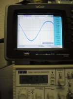
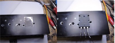
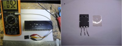
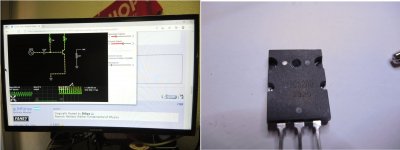
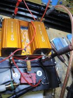
And just that you see that this what I type here is true, I took some time, took some components and Build your Circuit according to your last Simulation. Exactly that way,
I used another Transistor which fits better for a CLASS A
I used Double Voltage because with 9 Volts you will never hear any sound out of your Speakers.
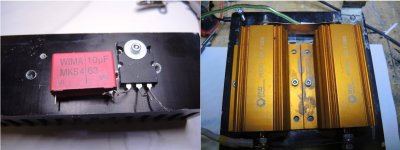
I used Huge Resistors with a resistance of 7.7 Ohm and since you are using 5% Components, the Resistor is just a good match. Tolerance is within this 5% it's even less.
Also I used a High Grade Cap at the input with 10Uf 63 Volts Non Polar.
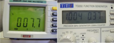
I hooked up Oscilloscope and Function Generator voltmeter Ohm Meter and all what one uses to test a circuit to get REAL MEASUREMENTS OUT OF IT, and not DREAMS like you do.
So check out the pics, and then start with the BASICS learn them.
Forget to talk about Distortion, rather inform yourself what an Resistor Array does, what an Resistor divider is meant for and that a LOAD Resistor for the COLLECTOR of a NPN Transistor isn't a equivalent for a SPEAKER and that the Circuit you try to build lacks of at least 2 Components.
At the Output you need to add a OUTPUT CAP to block DC off from the output signal
at the input it would take a BASE GND RESISTOR to lock input impedance to some certain level..
Then also you will need at least double voltage to have sound emitting from the Speaker. Good sound I mean not only Squeezed noise..
But the most important of all is, Listen to guys like John_Ellis, JMFAHEY and all the others who are trying to explain this for quite some time. These guys knowing what they talk about.
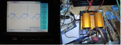
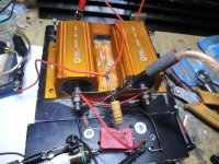
Enjoy Sunday and look a the pics I place here.. look good because these consists of some secrets I like you to find. And it's your Circuit in REALITY what you see in these Pics..
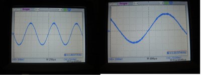
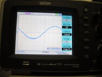
Also Note that up to Picture No 7 all Signals were measured with NO SPEAKER CONNECTED and then Check out Pic 8 ..
This way the sine wave is looking when connecting the speaker because there is not enough BIAS on the BASE of the Transistor..
If there are any mistakes in that documentation then let me know, where..
I apologize herewith already if this happens,, no one is perfect..
And it's Sunday
Good luck
Regards
Chris Hess
Actual components used:
1) 50V 10 uF non polarized capacitor
2) Resistor - -Brown- Black -Orange - Gold - 10k Ohm
3) Transistor - TIP 41A
The simulator plot taken across the 8 Ohm resistor, representing the speaker, is pretty ..... awful.
Sorry Vincent...
Hi BasicHIFI1
I think you do not understand what everyone here tries to say and teach you.
Go with the FUNDEMENTAL BASICS. This is were you show a big LACK of.
And just that you see that this what I type here is true, I took some time, took some components and Build your Circuit according to your last Simulation. Exactly that way,
I used another Transistor which fits better for a CLASS A
I used Double Voltage because with 9 Volts you will never hear any sound out of your Speakers.
I used Huge Resistors with a resistance of 7.7 Ohm and since you are using 5% Components, the Resistor is just a good match. Tolerance is within this 5% it's even less.
Also I used a High Grade Cap at the input with 10Uf 63 Volts Non Polar.
I hooked up Oscilloscope and Function Generator voltmeter Ohm Meter and all what one uses to test a circuit to get REAL MEASUREMENTS OUT OF IT, and not DREAMS like you do.
So check out the pics, and then start with the BASICS learn them.
Forget to talk about Distortion, rather inform yourself what an Resistor Array does, what an Resistor divider is meant for and that a LOAD Resistor for the COLLECTOR of a NPN Transistor isn't a equivalent for a SPEAKER and that the Circuit you try to build lacks of at least 2 Components.
At the Output you need to add a OUTPUT CAP to block DC off from the output signal
at the input it would take a BASE GND RESISTOR to lock input impedance to some certain level..
Then also you will need at least double voltage to have sound emitting from the Speaker. Good sound I mean not only Squeezed noise..
But the most important of all is, Listen to guys like John_Ellis, JMFAHEY and all the others who are trying to explain this for quite some time. These guys knowing what they talk about.
Enjoy Sunday and look a the pics I place here.. look good because these consists of some secrets I like you to find. And it's your Circuit in REALITY what you see in these Pics..
Also Note that up to Picture No 7 all Signals were measured with NO SPEAKER CONNECTED and then Check out Pic 8 ..
This way the sine wave is looking when connecting the speaker because there is not enough BIAS on the BASE of the Transistor..
If there are any mistakes in that documentation then let me know, where..
I apologize herewith already if this happens,, no one is perfect..
And it's Sunday
Good luck
Regards
Chris Hess
Attachments
-
 10.. Your Circuit VS reality.jpg183.5 KB · Views: 104
 -
 9. Your Circuit.jpg250.5 KB · Views: 105
 -
 8. Your Circuit.jpg347.9 KB · Views: 126
 -
 7. Your Circuit.jpg374.3 KB · Views: 104
 -
 6. Your Circuit.jpg230.7 KB · Views: 116
 -
 5. Your Circuit.jpg298 KB · Views: 108
 -
 4. Your Circuit.jpg272.9 KB · Views: 104
 -
 3. Your Circuit.jpg262.3 KB · Views: 152
 -
 2.Your Circuit.jpg258.6 KB · Views: 163
 -
 1. Your Circuit.jpg234.7 KB · Views: 153
Last edited:
May I add this here as well, I could clarify some misunderstandings
I need to add a few Pictures, because these Pics you see above are partly modified Circuit of BasicHifi1 -
His Original Circuit you can see here also with Readout, but it will definitely burn Speakers connected as he drew it..
His speaker is connected (R8Ohm) as he writes, to VRail - Vcollector without output Cap I understand that this is a no go.. Using the Loudspeaker as a LOAD RESISTOR for the collector I tried all of his approaches and none of them actually would give, in view to speakers, a safe connection that speaker wouldn't send out smoke signals sooner or later.
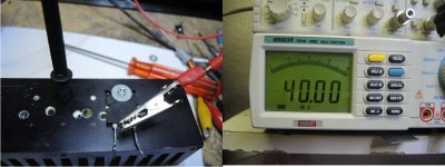
Just was curious about his approach of building this simple class a amp, which turns out to become a bit complicated.. that's why I used another way to get that collector fed with Power, and max DC-out is about 150mv - 300mv depends on Rail voltage used.. But I think it's still a need to connect a Output Cap. In picture 2 here you will see the Readout with the scope if connected like in Pic 4, and we are talking about 10 Volts DC when Rail is 18.VDC
Shown in the pictures in my earlier Post.
Reason that I have to make this here, is because Camera saved this few pics in a folder, which had only place for 5 more pics.. the rest from my last post, camera created a new folder, and I just saw a minute ago that these were missing .. now here you have them. I hope it helps that Basichifi1 gets his Class A.. Secret tip for you: Go to Firstwatt.com and check out what Nelson Pass is writing about Class A amps..
Sorry for the inconvenience.
Regards
Chris Hess
I need to add a few Pictures, because these Pics you see above are partly modified Circuit of BasicHifi1 -
His Original Circuit you can see here also with Readout, but it will definitely burn Speakers connected as he drew it..
His speaker is connected (R8Ohm) as he writes, to VRail - Vcollector without output Cap I understand that this is a no go.. Using the Loudspeaker as a LOAD RESISTOR for the collector I tried all of his approaches and none of them actually would give, in view to speakers, a safe connection that speaker wouldn't send out smoke signals sooner or later.
Just was curious about his approach of building this simple class a amp, which turns out to become a bit complicated.. that's why I used another way to get that collector fed with Power, and max DC-out is about 150mv - 300mv depends on Rail voltage used.. But I think it's still a need to connect a Output Cap. In picture 2 here you will see the Readout with the scope if connected like in Pic 4, and we are talking about 10 Volts DC when Rail is 18.VDC
Shown in the pictures in my earlier Post.
Reason that I have to make this here, is because Camera saved this few pics in a folder, which had only place for 5 more pics.. the rest from my last post, camera created a new folder, and I just saw a minute ago that these were missing .. now here you have them. I hope it helps that Basichifi1 gets his Class A.. Secret tip for you: Go to Firstwatt.com and check out what Nelson Pass is writing about Class A amps..
Sorry for the inconvenience.
Regards
Chris Hess
Attachments

- Home
- Amplifiers
- Solid State
- Simple Class A Amplifier Project