Zintolo,
I had a chance to run a number of sims on this circuit and others for comparison. My conclusions confirmed my initial guesses.
1. There are 2 parts to this: the driver and the final stage. They are only related by the driver requirement for a high swing at very light load.
2. The main attraction here is a (relatively) high DF for a PP amp with high power and low disctortion, without any GNFB. It does accomplish that very well. The price for it is some added complexity and the DF is not as high as can be attained with GNFB.
3. The actual topology of the power stage is not essential to those goals. Any way you can apply lots of local feedback, to both g1 and g2, will result in low Zout. This topology is, however, one of the best ways of doing it.
4. The topology of the driver is also not essential. For example, I was able to get similar results with a single stage driver consisting of a pentode LTP. I used Pete Millett's "PPP807 driver" without the first stage and I was able to produce the same swing and distortion. I was also able to apply a-g feedback to a conventional power stage by using this driver. But again, your shunt cascode does do its job very well.
5. I do think that both the driver and the power stage of your circuit have the potential for further refinement and may possibly lead to performance beyond what can be done with other topologies. We'll have to see.
Ultimately, I don't think it's capable of the same DF as an amp with lots of GNFB. Whether an amp with local FB is better than one with global FB and more DF, I don't know. That's a religious debate. But when you're all done, you can always add some GNFB on top of it all.
Looking forward to your progress.
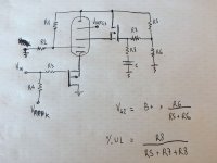
I post here an upgrade to this UNSET+UL design, in order to adapt it to whatever tube and to be able to use a standard output transformer without UL taps, so to avoid all possible distortions coming from the transformer: it is just the pentode linearizing itself by correcting g1 through R1 and R2, and correcting g2 through R5 R7 and R8. It has to follow the following rule:
R2 / (R1+R2) = R8 / (R5 + R7 + R8)

R2 / (R1+R2) = R8 / (R5 + R7 + R8)
Attachments
Last edited:
The previous post is the "morning shower idea", not simulated yet, so it could have something wrong in it.
Thanks for the time you dedicated to this circuit. I really appreciate!Zintolo,
I had a chance to run a number of sims on this circuit and others for comparison. My conclusions confirmed my initial guesses.
I won't probably be the "all speakers & all genres" kind of amp, but I have to say it's the best design I've done so far, and it's simpler than others I've built.2. The main attraction here is a (relatively) high DF for a PP amp with high power and low disctortion, without any GNFB. It does accomplish that very well. The price for it is some added complexity and the DF is not as high as can be attained with GNFB.
Thanks!3. The actual topology of the power stage is not essential to those goals. Any way you can apply lots of local feedback, to both g1 and g2, will result in low Zout. This topology is, however, one of the best ways of doing it.
I wasn't aware of Pete Millet's design, I will search for it and see. I will also try to simulate the circuit of the post above for the LTP as well, it would be nice to apply the same concept to the driver as well.4. The topology of the driver is also not essential. For example, I was able to get similar results with a single stage driver consisting of a pentode LTP. I used Pete Millett's "PPP807 driver" without the first stage and I was able to produce the same swing and distortion. I was also able to apply a-g feedback to a conventional power stage by using this driver. But again, your shunt cascode does do its job very well.
I totally agree with you. I'm a Mechanical Engineer and so I don't have the deep electronic knowledge to understand how to optimize circuits beyond a certain level. Maybe a 10% local nfb can give more margin to add gnfb (the other triode on the LTP is there just for that purpose) and increase DF plus reduce THD even further. I would like to see it go even further if possible, and thanks to the contribution of you all it is already more steps above in what I would have been able to do alone.5. I do think that both the driver and the power stage of your circuit have the potential for further refinement and may possibly lead to performance beyond what can be done with other topologies. We'll have to see.
I've designed guitar and bass amps for me and friends since early 2000, so probably I've a different approach to Hi-Fi. What I've found I like most is not absolutely no distortion, but an amps that goes euphonically into distortion. That said, most probably the best way to get low distortion is optimising tubes with local feedback and then "iron" last small residual distortions with some gnfb, but the right balance of all the ratios of different nfbs is something beyond my knoledge by now, and just local nfb is easier.Ultimately, I don't think it's capable of the same DF as an amp with lots of GNFB. Whether an amp with local FB is better than one with global FB and more DF, I don't know. That's a religious debate. But when you're all done, you can always add some GNFB on top of it all.
Is there anyone that can help with the layout or pcb of this amp?Looking forward to your progress.
Targetting low THD and high DF, probably a LTP built with the CORONA gain stage (CCS loaded pentode) with local feedback driving the power amp with local feedback could be a good candidate.
The PCB for the driver will be ready soon. The high gain, and need for good control of the base voltage makes the PCB implementation critical, for good results. i can do a PCB for the output stage, as a separate item, if that helps. Separate boards mean that you can compare other driver architectures, also.
In a true UL output stage that uses an output transformer the plate voltage will be lower than the screen grid voltage at the moment of peak conduction in the tube, as the CT of the OPT is tied to B+.
The circuits shown in posts #76 and #82 are not capable of doing this which will cause distortion under large signal conditions.
See post #22 in this thread, and look over the entire thread for a discussion of this concept.
Adjustable distributed load discussion
The circuits shown in posts #76 and #82 are not capable of doing this which will cause distortion under large signal conditions.
See post #22 in this thread, and look over the entire thread for a discussion of this concept.
Adjustable distributed load discussion
Rod,
thank you for your offer! Let me post the full schematic as I'll have finished it!
George,
thanks to point me to that thread, I will read it and revert here with some more (hopefully good) ideas, even if most probably you already have the full scenario in your head.
thank you for your offer! Let me post the full schematic as I'll have finished it!
George,
thanks to point me to that thread, I will read it and revert here with some more (hopefully good) ideas, even if most probably you already have the full scenario in your head.
We can solve this simply by connecting the output transformer to the right part of circuit at post #82 (the nmosfet side), then add a 10 Ohm resistor between the nmosfet and pentode's plate. It could also become useful to measure bias.In a true UL output stage that uses an output transformer the plate voltage will be lower than the screen grid voltage (omissi) circuits shown in posts #76 and #82 are not capable of doing this which will cause distortion under large signal conditions.
Targetting low THD and high DF, probably a LTP built with the CORONA gain stage (CCS loaded pentode) with local feedback driving the power amp with local feedback could be a good candidate.
I haven't measured the Zout of that amp at the output tube plate, but I have estimated that it must be 25 Ohms or less. The output transformer copper losses are the most significant contributor to Zout in that amp by far.
That feedback scheme could work very well with one of these toroid output transformers if one wanted to make a very low Zout amp without a global loop.
Yes, it’s this transformer: TTG-KT88PP - Tube output transformer [4kOhm] 2xKT88 / 2x300B Push-pull or similar - Shop Toroidy.pl
but with 500 mA primary and 23% UL taps.
but with 500 mA primary and 23% UL taps.
In a true UL output stage that uses an output transformer the plate voltage will be lower than the screen grid voltage at the moment of peak conduction in the tube, as the CT of the OPT is tied to B+.
Morning shower made me understand I was totally wrong with this statement:
We can solve this simply by connecting the output transformer to the right part of circuit at post #82 (the nmosfet side), then add a 10 Ohm resistor between the nmosfet and pentode's plate. It could also become useful to measure bias.
I realized George was not talking about zero signal status, but full signal, when plate is at 100% its swing, whilst screen at 20-40% of it, so screen is 80-60% higher, and that circuit cannot do it.
So the schematic at post #82 works well with tubes like GU50 where screen are at 270V and plates at 900V (so if the plate goes down to 100V, 23%UL screen goes down to 270 - [(900-100)*0.23] = 86 V.
What I'd like in setting the voltage and swing of the screens independently, is that we can also "target" how the tube enters into distortion (by moving up and down the g1=0 knee), and also decrease the swing requirements by lowering screen voltage.
I still haven't read all the thread you suggested, George, but I will tonight.
Yes, if you want full control of the % fb signal you apply to g1 and g2, the ac signal is easy to control as a ratio of anode ac voltage. But you have to be careful with the dc bias. 50% fb does not necessarily mean 50% ac AND 50% dc.
Thanks dgta, it will probably be an evolution of schematic at post #82 by referring the mosfet to B+ (plus something more, depending on how much class A I have) instead of the plate. I will elaborate it more.
Last edited:
Morning shower made me understand I was totally wrong with this statement:
Hehe! I wish my showers were that enlightening and clarifying! BTW, very interesting thread!
I realized George was not talking about zero signal status, but full signal, when plate is at 100% its swing, whilst screen at 20-40% of it, so screen is 80-60% higher, and that circuit cannot do it.
So the schematic at post #82 works well with tubes like GU50 where screen are at 270V and plates at 900V (so if the plate goes down to 100V, 23%UL screen goes down to 270 - [(900-100)*0.23] = 86 V.
What I'd like in setting the voltage and swing of the screens independently, is that we can also "target" how the tube enters into distortion (by moving up and down the g1=0 knee), and also decrease the swing requirements by lowering screen voltage.
Roberto, if I understand correctly, you are interested in modulating the screen voltage to target how the tube enters into distortion. This reminds of Dave Gillespie’s efforts with Enhanced Fixed Bias (EFB)tm. However, in EFB Dave’s goal is to modulate the bias voltage, as well as screen voltage according to variations (sag) in B+ as signal level increases. If you are not familiar with EFB it may be worthwhile to review his article on his Dyna SCA modification and the significant distortion reduction he measured. Dave had subsequently published several modifications of classic amps applying EFB to them in audiokarma.org
http://tronola.com/A_New_Look_At_An_Old_Friend.pdf
Thank you Francois!
Yes, I want to be able to change the dc reference for the screens and modulate it with a percentage of anode swing to it.
I'll read the thread you just suggested, in the meanwhile I've found this: Adjustable distributed load discussion
Yes, I want to be able to change the dc reference for the screens and modulate it with a percentage of anode swing to it.
I'll read the thread you just suggested, in the meanwhile I've found this: Adjustable distributed load discussion
a floating 250V supply available to connect from the plate to the B++ drain supply point
Hi dgta, I would like to ask you some details.4. The topology of the driver is also not essential. For example, I was able to get similar results with a single stage driver consisting of a pentode LTP. I used Pete Millett's "PPP807 driver" without the first stage and I was able to produce the same swing and distortion.
I've found the schematic here: Push-pull driver board

Which tubes you used for that single stage, and did you apply some different values or modification?
I would like to simulate this driver stage as well to see differences.
Thanks in advance
Same tubes, but I was able to get similar results with other tubes. I used pretty much his exact circuit, adjusted for A-G feedback, which you implement differently. I'm sure you can refine/optimize it for other goals. Here is the .asc file. The second file is the same driver with a very conventional power stage so you can do some comparisons.
Keep in mind he didn't intend this to be a one-stage driver. If you add his 6J4 front end and the corresponding additional amount of GNFB, both distortion and Zo improve by an order of magnitude, as you would expect.
Edit: The tube suffix "ay" simply means I used the Ayumi models.
Keep in mind he didn't intend this to be a one-stage driver. If you add his 6J4 front end and the corresponding additional amount of GNFB, both distortion and Zo improve by an order of magnitude, as you would expect.
Edit: The tube suffix "ay" simply means I used the Ayumi models.
Attachments
Last edited:
Thank you very much dgta,
I will simulate those circuits.
This evening I did some simulations to use this circuit with EL34 and a power transformer I already have, again with the same combined 23% a-g1 and UL.
I've obtained around 9 Wrms in class A and 60 Wrms in class AB1, a Zout of 1.93 Ohm (DF 4.14) with 6.6 kOhm Raa and 500 V B+ (that's 385 across the EL34 with around 52 mA plate current).
You can still increase the damping factor further using local Fdbk.
Put a small current sense resistor in the M1 & M2 P type Mosfet drains. Then feed those signals back to the driver in such a way as to increase the appropriate drive V just enough to make up for resistive loss in the OT primary. (positive current derived Fdbk obviously)
One could try to go further and remove the secondary IR loss too, but the sensed currents contain the OT magnetizing current, which is only felt by the primary side resistance, so you would end up injecting some inverted magnetizing distortion then.
Unfortunately, the non-inverting form of the drive system here doesn't make for an easy insertion point (has to become positive Fdbk, but the Mosfet drain has already inverted it). Some ingenuity required. One can flip the P-P current feedbacks around to get the phasing corrected if a convenient insertion point is found. For simulation purposes, one could put smallish resistors under the input grid bias supplies, or ground reference points, for inserting the sensed current Fdbks.
Last edited:
- Home
- Amplifiers
- Tubes / Valves
- Shunt Cascode Driver meets UNSET for Push-Pull