Sorry for the question that could be well known to most, but not to me. Ayumi models fit better than others?Edit: The tube suffix "ay" simply means I used the Ayumi models.
Thanks
I will see how to implement it, thanks for the hint!Put a small current sense resistor in the M1 & M2 P type Mosfet drains. Then feed those signals back to the driver in such a way as to increase the appropriate drive V just enough to make up for resistive loss in the OT primary. (positive current derived Fdbk obviously)
Thanks again!For simulation purposes, one could put smallish resistors under the input grid bias supplies, or ground reference points, for inserting the sensed current Fdbks.
Looks like one could insert the current corrections at the Q1 & Q2 bases also, except for the significant positive V there. Maybe use cap coupling. Use-able for a final design at that location at least.
Hmm, another possible location would be the ground references for the output grids at R4 and R6 ground connections. Just move them up (individually) to the sense R's instead. No caps needed there. Can't get more local than that!
Hmm, another possible location would be the ground references for the output grids at R4 and R6 ground connections. Just move them up (individually) to the sense R's instead. No caps needed there. Can't get more local than that!
Last edited:
I was thinking about a RCA-50W-like plates to driver cathodes feedback with a pair of resistors in series (because of the voltage rating) from power tubes' plates to U1's sides (like R22 and R23 here: https://www.angelfire.com/vt/audio/rca50wdia.gif )
Of course the CCS on the tail of the LTP needs to take into account of that extra current.
I've also a pair of 6k6 Raa 23%UL output transformers that could be used with EL34. I've just dropped in the EL34 without optimisation and I've got 60Wrms with a B+ of 500V and a Zout of 1.93 Ohms (DF of 4.13).
Attachments
...Ayumi models fit better than others?
Thanks
The Ayumi models were published here and there are models for many tubes. I'd say they are probably the most widely available. I can't generalize on how well they fit, some fit better than others.
Some more recent modeling work, including by several members here, have produced individual models that are more accurate. But I'm not an expert. Check the long thread on this topic.
Hi dgta, sorry to bother you.
I've one missing component on your Millet4post file. Is it this one: Vacuum Tube SPICE Models ?
Thanks again
Roberto
PS
I've bought four gm matched 6N23P (6Н23П) to experiment, I will define other components and post the full schematic soon to have a final check before buying all missing parts.
I've one missing component on your Millet4post file. Is it this one: Vacuum Tube SPICE Models ?
Thanks again
Roberto
PS
I've bought four gm matched 6N23P (6Н23П) to experiment, I will define other components and post the full schematic soon to have a final check before buying all missing parts.
Last edited:
I'm finalizing the components to perform some early tests, so I'll pose some (probably newbie) questions on SS devices:
As for the high voltage regulation: is this circuit from tubecad ( Shunt Regulators )
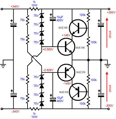
Something I can use for the driver's asymmetrical voltage (+200 & -240Vdc) PSU?
Is there anything better/simpler for this purpose?
As for the BJT of the driver, I'd chose this one because it should easily handle the needed 1W thermal dissipation:
https://www.mouser.it/datasheet/2/308/1/MJE5850_D-2315747.pdf
Is there any drawback you can see and I don't?
As for the cathode driver pmosfet, I'do go for this one:
https://www.mouser.it/datasheet/2/308/1/FQPF11N40C_D-2313913.pdf
Again, any cons about it?
Are these heatsinks 588-FA-T220-64E with 3 K/W:
https://www.mouser.it/datasheet/2/303/sink_f_r-1265536.pdf
enough for one bjt and one pmosfet, or +60°C (that's 20W multiplied by 3°C/W) is too much?
Thank you all in advance
As for the high voltage regulation: is this circuit from tubecad ( Shunt Regulators )
Something I can use for the driver's asymmetrical voltage (+200 & -240Vdc) PSU?
Is there anything better/simpler for this purpose?
As for the BJT of the driver, I'd chose this one because it should easily handle the needed 1W thermal dissipation:
https://www.mouser.it/datasheet/2/308/1/MJE5850_D-2315747.pdf
Is there any drawback you can see and I don't?
As for the cathode driver pmosfet, I'do go for this one:
https://www.mouser.it/datasheet/2/308/1/FQPF11N40C_D-2313913.pdf
Again, any cons about it?
Are these heatsinks 588-FA-T220-64E with 3 K/W:
https://www.mouser.it/datasheet/2/303/sink_f_r-1265536.pdf
enough for one bjt and one pmosfet, or +60°C (that's 20W multiplied by 3°C/W) is too much?
Thank you all in advance
I haven't studied that regulator but a shunt regulator would probably not be my first choice. Not enough info to offer an informed opinion.
I would first decide on an amp circuit, optimize it as much as possible (including some thought to power supply requirements) and breadboard it. Use lab supplies to provide all necessary voltages. Testing will probably result in some circuit changes and those may change the supply requirements. Once the amp is running the way you want it, then you can come up with the simplest supply scheme that meets the requirements.
I would first decide on an amp circuit, optimize it as much as possible (including some thought to power supply requirements) and breadboard it. Use lab supplies to provide all necessary voltages. Testing will probably result in some circuit changes and those may change the supply requirements. Once the amp is running the way you want it, then you can come up with the simplest supply scheme that meets the requirements.
Thanks dgta,
yesterday evening I've done some simulations and Millett's pentode preamp seems to behave better on overloads (I can reach around 95 Wrms at less than 5% THD keeping a 1/10 ratio between one odd harmonic and the next one).
I'd like to implement the CCS loaded pentodes with a-g1 plus UL (via n-mosfet) on the LTP as well, but I can't see how to do it with a CCS on the bottom as well (to avoid the expensive input transformer as done here: If UNSET and the RCA50W Had a Baby ). Will a simple CCS on top and shunt CCS on bottom make the latter preveal?
I just link here a schematic posted by Wavebourn that could be useful for some considerations on nested feedback, even if I'd prefer a two stage amp:
Schade Feedback In A Push Pull Differential Amplifier?

Schade Feedback In A Push Pull Differential Amplifier?
I'd like to implement the CCS loaded pentodes with a-g1 plus UL (via n-mosfet) on the LTP as well, but I can't see how to do it with a CCS on the bottom as well (to avoid the expensive input transformer as done here: If UNSET and the RCA50W Had a Baby ). Will a simple CCS on top and shunt CCS on bottom make the latter preveal?
If you have some high-value resistors in parallel with the loads like I had in that other thread, three CCSs should work. They just get set so that the difference in current is what passes in the resistors.
Alternatively, the resistors can go from plate to GND, which I would think would give better PSRR.
Thank you SpreadSpectrum!
I will try that option as well, at least I will try to sketch it and propose it here.
In this case my goal, as is probably clear, is to linearize the pentodes of the the LTP as I've done for the KT88, plus have your CCS loaded extra gain to get linearity and DF as well. ...or better: to be able to have a very low THD before applying any feedback, then have high gain so high DF available if needed.
If you don't like the input transformer in the sketch I made that you cited above, another alternative could be to have a concertina as the first stage of the amplifier. It could probably just stay outside of all feedback loops since it would be very low distortion anyway. I'd be tempted to use a mosfet for that.
I just like the Jensen transformers, but they aren't a requirement to do something like this.
I just like the Jensen transformers, but they aren't a requirement to do something like this.
It's more related to their price than to the fact of not having an input transformer per se.
I (do my best to) avoid preconcepts as much as possible.
I will try your suggestion of the mosfet as well, but first of all I will post the two possible schematics with Rod's and Peter preamps.
I (do my best to) avoid preconcepts as much as possible.
I will try your suggestion of the mosfet as well, but first of all I will post the two possible schematics with Rod's and Peter preamps.
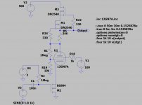
I just sketched (I underline "sketched" because most probably it will break some limits of the valves and it can be deeply improved) half of the driver I had in mind, in order to give an idea of what I have in mind.
I've used the resistor in parallel with the CCS as a a-g1 feedback as well.
I can get 360Vpp with 0,24% THD with 1.8Vp at its input. More than what is needed for the KT88s.

It seems there's not even need to apply the same concept of a-g1&UL feedback for the driver.
It needs to be optimized and converted in a PI, but seems very promising.
I've used the resistor in parallel with the CCS as a a-g1 feedback as well.
I can get 360Vpp with 0,24% THD with 1.8Vp at its input. More than what is needed for the KT88s.
Code:
Harmonic	Frequency	 Fourier 	Normalized	 Phase  	Normalized
 Number 	  [Hz]   	Component	 Component	[degree]	Phase [deg]
    1   	1.000e+03	1.803e+02	1.000e+00	    0.06°	    0.00°
    2   	2.000e+03	4.232e-01	2.347e-03	  -89.46°	  -89.52°
    3   	3.000e+03	1.013e-01	5.621e-04	    0.91°	    0.85°
    4   	4.000e+03	3.482e-02	1.931e-04	   91.56°	   91.51°
    5   	5.000e+03	1.243e-02	6.897e-05	 -178.55°	 -178.60°
    6   	6.000e+03	4.249e-03	2.357e-05	  -90.27°	  -90.33°
    7   	7.000e+03	1.323e-03	7.338e-06	    2.21°	    2.15°
    8   	8.000e+03	5.055e-04	2.804e-06	  105.07°	  105.01°
    9   	9.000e+03	2.619e-04	1.453e-06	 -178.47°	 -178.52°
   10   	1.000e+04	1.021e-04	5.664e-07	 -148.62°	 -148.68°
Total Harmonic Distortion: 0.242227%(0.242227%)
It seems there's not even need to apply the same concept of a-g1&UL feedback for the driver.
It needs to be optimized and converted in a PI, but seems very promising.
Attachments
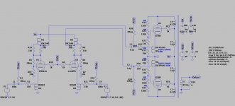
I anticipate here what I'll propose this evening for the driver:
- the circuit above with a single 10M90S CCS;
- feedback a-g1 as above;
- input on the pmosfet as above;
- feedback from KT88s plates to drivers' screens through voltage dividers joined into a CCS to ground (à la SpreadSpectrum's UNSET&RCA);
- if there will be any need, there's the possibility to apply global feedback on the pmosfet of the complementary 12GN7A of the PI/DRIVER.
The advantage I see is that it should have a very good PSRR, so PSU should be simpler as well. As I said, I'd like it to be a well performing plus cheap amp to build.
Thanks to everyone has contributed up to now, and that will help me further.
Roberto
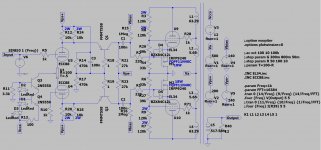
I've had no time to work on this, but that's what I was simulating.
It needs an input transformer (the same can be used for SE without input transformer). Can you suggest a good input transformer that will not costs an arm and a leg? I've seen Nelson pass using some pcb mounted ones on his amps.

THD at 1 Wrms (yes, parts per million):
THD at 10 Wrms:
THD at 83 Wrms:
It needs an input transformer (the same can be used for SE without input transformer). Can you suggest a good input transformer that will not costs an arm and a leg? I've seen Nelson pass using some pcb mounted ones on his amps.
THD at 1 Wrms (yes, parts per million):
Code:
Harmonic	Frequency	 Fourier 	Normalized	 Phase  	Normalized
 Number 	  [Hz]   	Component	 Component	[degree]	Phase [deg]
    1   	1.000e+03	4.027e+00	1.000e+00	  179.88°	    0.00°
    2   	2.000e+03	3.306e-05	8.208e-06	    6.75°	 -173.12°
    3   	3.000e+03	2.395e-04	5.948e-05	 -178.08°	 -357.96°
    4   	4.000e+03	1.645e-05	4.086e-06	   -0.02°	 -179.90°
    5   	5.000e+03	1.331e-05	3.306e-06	    0.07°	 -179.81°
    6   	6.000e+03	1.097e-05	2.723e-06	   -0.00°	 -179.88°
    7   	7.000e+03	9.400e-06	2.334e-06	   -0.00°	 -179.88°
    8   	8.000e+03	8.226e-06	2.043e-06	   -0.00°	 -179.88°
    9   	9.000e+03	7.312e-06	1.816e-06	   -0.00°	 -179.88°
   10   	1.000e+04	6.580e-06	1.634e-06	   -0.00°	 -179.88°
Total Harmonic Distortion: 0.006047%(0.006068%)
THD at 10 Wrms:
Code:
Harmonic	Frequency	 Fourier 	Normalized	 Phase  	Normalized
 Number 	  [Hz]   	Component	 Component	[degree]	Phase [deg]
    1   	1.000e+03	1.263e+01	1.000e+00	  179.88°	    0.00°
    2   	2.000e+03	1.615e-04	1.278e-05	   51.39°	 -128.49°
    3   	3.000e+03	8.278e-03	6.552e-04	 -178.17°	 -358.05°
    4   	4.000e+03	5.190e-05	4.108e-06	   -2.44°	 -182.32°
    5   	5.000e+03	9.546e-05	7.556e-06	    3.25°	 -176.63°
    6   	6.000e+03	3.446e-05	2.727e-06	   -0.09°	 -179.97°
    7   	7.000e+03	2.828e-05	2.239e-06	   -0.42°	 -180.30°
    8   	8.000e+03	2.584e-05	2.046e-06	   -0.15°	 -180.03°
    9   	9.000e+03	2.301e-05	1.821e-06	   -0.12°	 -180.00°
   10   	1.000e+04	2.067e-05	1.636e-06	   -0.12°	 -179.99°
Total Harmonic Distortion: 0.065536%(0.065538%)
THD at 83 Wrms:
Code:
Harmonic	Frequency	 Fourier 	Normalized	 Phase  	Normalized
 Number 	  [Hz]   	Component	 Component	[degree]	Phase [deg]
    1   	1.000e+03	3.644e+01	1.000e+00	  179.86°	    0.00°
    2   	2.000e+03	1.673e-02	4.590e-04	   89.26°	  -90.60°
    3   	3.000e+03	4.241e-01	1.164e-02	 -178.21°	 -358.07°
    4   	4.000e+03	9.288e-03	2.549e-04	  -89.81°	 -269.67°
    5   	5.000e+03	8.947e-02	2.455e-03	    1.91°	 -177.95°
    6   	6.000e+03	6.328e-03	1.737e-04	   86.36°	  -93.49°
    7   	7.000e+03	2.914e-02	7.996e-04	  179.85°	   -0.01°
    8   	8.000e+03	5.057e-03	1.388e-04	  -93.75°	 -273.61°
    9   	9.000e+03	1.210e-02	3.322e-04	   -4.19°	 -184.04°
   10   	1.000e+04	4.476e-03	1.228e-04	   83.28°	  -96.58°
Total Harmonic Distortion: 1.194115%(1.195247%)
Attachments
THD at 40 Wrms:
As a comparison, the shunt cascode simulates this way (https://www.diyaudio.com/forums/tub...iver-meets-unset-push-pull-post6658251.html):
1 Wrms:
42Wrms:
80 Wrms:
From what I understand and know, on paper it's a better slope of harmonics than with CCS loaded pentodes driver.
Any comment?
Code:
Harmonic	Frequency	 Fourier 	Normalized	 Phase  	Normalized
 Number 	  [Hz]   	Component	 Component	[degree]	Phase [deg]
    1   	1.000e+03	2.510e+01	1.000e+00	  179.87°	    0.00°
    2   	2.000e+03	1.342e-03	5.346e-05	   82.44°	  -97.43°
    3   	3.000e+03	7.643e-02	3.045e-03	 -178.03°	 -357.90°
    4   	4.000e+03	1.748e-04	6.963e-06	  -50.78°	 -230.65°
    5   	5.000e+03	3.304e-03	1.316e-04	    4.52°	 -175.35°
    6   	6.000e+03	7.073e-05	2.817e-06	   16.95°	 -162.92°
    7   	7.000e+03	3.272e-04	1.303e-05	 -175.14°	 -355.01°
    8   	8.000e+03	5.191e-05	2.068e-06	   -4.12°	 -183.99°
    9   	9.000e+03	9.230e-05	3.677e-06	    1.37°	 -178.50°
   10   	1.000e+04	4.127e-05	1.644e-06	   -0.01°	 -179.88°
Total Harmonic Distortion: 0.304821%(0.304821%)
As a comparison, the shunt cascode simulates this way (https://www.diyaudio.com/forums/tub...iver-meets-unset-push-pull-post6658251.html):
1 Wrms:
Code:
Harmonic	Frequency	 Fourier 	Normalized	 Phase  	Normalized
 Number 	  [Hz]   	Component	 Component	[degree]	Phase [deg]
    1   	1.000e+03	3.921e+00	1.000e+00	   -0.77°	    0.00°
    2   	2.000e+03	2.642e-04	6.737e-05	  -93.89°	  -93.11°
    3   	3.000e+03	3.495e-04	8.913e-05	    2.21°	    2.99°
    4   	4.000e+03	4.938e-06	1.259e-06	  173.87°	  174.64°
    5   	5.000e+03	4.051e-06	1.033e-06	  175.50°	  176.28°
    6   	6.000e+03	3.280e-06	8.365e-07	  175.75°	  176.53°
    7   	7.000e+03	2.812e-06	7.172e-07	  176.39°	  177.16°
    8   	8.000e+03	2.453e-06	6.255e-07	  176.94°	  177.72°
    9   	9.000e+03	2.177e-06	5.552e-07	  177.28°	  178.06°
Total Harmonic Distortion: 0.011174%(0.011144%)
42Wrms:
Code:
Harmonic	Frequency	 Fourier 	Normalized	 Phase  	Normalized
 Number 	  [Hz]   	Component	 Component	[degree]	Phase [deg]
    1   	1.000e+03	2.599e+01	1.000e+00	   -0.80°	    0.00°
    2   	2.000e+03	1.106e-02	4.254e-04	  -92.04°	  -91.24°
    3   	3.000e+03	1.181e-01	4.545e-03	    2.81°	    3.61°
    4   	4.000e+03	1.003e-04	3.858e-06	   99.03°	   99.82°
    5   	5.000e+03	4.331e-03	1.666e-04	 -170.76°	 -169.97°
    6   	6.000e+03	6.877e-05	2.645e-06	  100.98°	  101.78°
    7   	7.000e+03	5.625e-04	2.164e-05	   12.39°	   13.19°
    8   	8.000e+03	3.805e-05	1.464e-06	  103.35°	  104.15°
    9   	9.000e+03	7.935e-05	3.052e-06	  162.45°	  163.25°
Total Harmonic Distortion: 0.456776%(0.456775%)
80 Wrms:
Code:
Harmonic	Frequency	 Fourier 	Normalized	 Phase  	Normalized
 Number 	  [Hz]   	Component	 Component	[degree]	Phase [deg]
    1   	1.000e+03	3.597e+01	1.000e+00	   -0.83°	    0.00°
    2   	2.000e+03	2.179e-02	6.059e-04	  -91.90°	  -91.07°
    3   	3.000e+03	4.654e-01	1.294e-02	    3.22°	    4.06°
    4   	4.000e+03	5.609e-04	1.560e-05	   89.59°	   90.42°
    5   	5.000e+03	7.209e-02	2.004e-03	 -173.66°	 -172.82°
    6   	6.000e+03	1.214e-04	3.375e-06	   99.40°	  100.23°
    7   	7.000e+03	1.778e-02	4.943e-04	    7.09°	    7.92°
    8   	8.000e+03	7.186e-05	1.998e-06	   92.02°	   92.85°
    9   	9.000e+03	3.179e-03	8.839e-05	 -170.70°	 -169.87°
Total Harmonic Distortion: 1.311753%(1.311753%)
From what I understand and know, on paper it's a better slope of harmonics than with CCS loaded pentodes driver.
Any comment?
- Home
- Amplifiers
- Tubes / Valves
- Shunt Cascode Driver meets UNSET for Push-Pull