I've tried to join the two cathodes and then CCS them, then bias the gates of the pmosfet, but it wasn't performing correctly. Most probably I did something wrong. That's it.
I will try it again.
I will try it again.
Well, I'm not sure what your overall strategy is. Seems like you are going in multiple directions since the beginnning of the thread. As to this latest schematic, it seems to me you would want to make the first stage a differential amplifier as opposed to 2 independent amps. Even if you dual-drive it from a transformer, I would still make it at least a short tail pair. But I don't know the goals and strategy.
Yes, power amp is fixed eith a-g1 plus UL, whilst I’m still comparing ccs-loaded pentode Pi/driver (I will retry LTP) vs shunt cascode LTP. Shunt cascode seems superior (low order harmonics when overloaded) even if THD is higher on the whole range.
I would prefer to have a LTP in both cases.
I still need to optimize the pentode LTP that would mean an easier power supply, if same results can be obtained.
I would prefer to have a LTP in both cases.
I still need to optimize the pentode LTP that would mean an easier power supply, if same results can be obtained.
In any push-pull amp, there will be imbalances between the two sides. LTP input is a great way to solve this for that stage. It still leaves imbalances in the two sides of the output stage unaccounted for and uncorrected. What does a perfectly balanced phase splitter get you if subsequent stages don't have the same degree of balance?
Some of the older amps would have a phase splitter that you could purposely introduce imbalance into by adjusting a pot to try to cancel the imbalances of the later stages. My Fisher amp service manual said to connect a distortion analyzer to each channel and adjust the AC balance pot for minimum distortion. I took this approach on a couple of push-pull amps that I built but it probably requires periodic adjustment as tubes age.
I've been looking at building something similar to the input stage of an instrumentation amplifier to account and correct for imbalances in the whole amp. That's what I was attempting in that sketch I made for a modern take on the RCA 50W amp, with some of George's ideas thrown in. I'm looking for something that works really well and doesn't require an adjustment.
A lot of this imbalance stuff won't show up in simulations unless you create it in the sims to see what happens.
It looks like you have tried out a lot of interesting ideas. I can't wait to see more.

I'm looking for something that works really well and doesn't require an adjustment.
GNFB 🙂
May I ask you how it would be?I've been looking at building something similar to the input stage of an instrumentation amplifier to account and correct for imbalances in the whole amp.
Thanks, just ideas by now. I want to find what is the best way to drive the power amp. I think I've almost optimized the shunt cascoded driver, but I'm far from it for the pentode version.It looks like you have tried out a lot of interesting ideas. I can't wait to see more.
What I'll try to simulate next is blending:
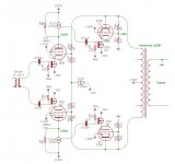
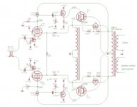
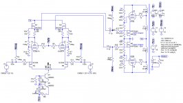
This idea of driving the screens of the LPT and balancing it through screens: Long Tail Pair Phase Inverter with Pentode?
This way: Shunt Cascode Driver meets UNSET for Push-Pull
This CCS-loaded pentode driver with a-g1 feedback (same % as g2 feedback, as I've done for the KT88s) as a LTP: Shunt Cascode Driver meets UNSET for Push-Pull
Well, with 3 MOSFETs per tube, they will probably have to move you to the solid state section...😀
Ahahah! I would be discriminated there as well, implementing those old inefficient pieces of glass ruining SS perfection!
Best amp I've built so far is a personal variation of the BH84, and over there the SS to tube ratio is 8/3 per channel. Here it would be 8/3 as well with shunt feedback, otherwise 6/4 (if I use nested feedback from KT88's a to driver's g2) or 8/4 (with the solution above) with CCS pentodes.
Using the same local feedback solution on both stages would be nice, that's why I'm still investigating it, even if the shunt cascode is still my favourite, at the moment.
Time ago I simulated an hybrid CCS-loaded cascode with triode on the bottom (CED/UNSET/CORONA-like ECC88 hybrid cascoded driver) capable of 140Vpp at a THD of 0.047%, but if I propose it here you'll ban me from this section (and I'd agree!) 😀
May I ask you how it would be?
I've attached a picture from Wikipedia of the instrumentation amplifier configuration, the two leftmost amplifiers represent what I'm trying to accomplish conceptually. The output stage is replaced with the output transformer.
In a normal push-pull amplifier configuration, the output is taken from the plates, so there is a large DC offset so my solution for that was to use a CCS to provide a high AC impedance node that would pull the feedback divider down to a voltage where it could be attached to one input of the input stage.
Things are way easier in an amp like my Unity-Coupled amp where feedback can be taken from the cathodes which are near ground potential at idle.
By the way, you can probably get more open loop gain and less distortion out of these CCS-loaded stages by connecting the feedback resistor to the source of the lower CCS mosfet. Might be interesting to see what kind of difference it makes.
Edit: Hmmm, it seems that the forum software didn't like the image from Wikipedia. Here's a link.
Attachments
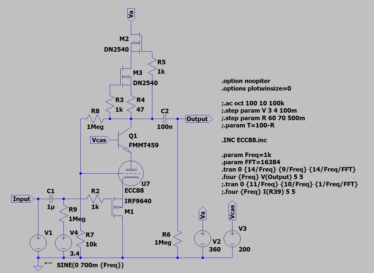
I've done some simulations and there's no need to implement another pair of BJT in the LTP, the THD is still very low at max power:
This is the output:

I have a newbie question but... I still can't make the LTP work without adding a signal out of phase on the opposite side of the LTP... what am I missing?
Code:
Harmonic	Frequency	 Fourier 	Normalized	 Phase  	Normalized
 Number 	  [Hz]   	Component	 Component	[degree]	Phase [deg]
    1   	1.000e+03	1.241e+02	1.000e+00	    0.06°	    0.00°
    2   	2.000e+03	7.976e-02	6.429e-04	  -90.28°	  -90.34°
    3   	3.000e+03	4.562e-02	3.677e-04	    2.93°	    2.87°
    4   	4.000e+03	4.649e-03	3.747e-05	   98.11°	   98.05°
    5   	5.000e+03	2.639e-03	2.127e-05	 -169.18°	 -169.24°
    6   	6.000e+03	4.260e-04	3.433e-06	 -106.88°	 -106.94°
    7   	7.000e+03	1.639e-04	1.321e-06	  106.61°	  106.54°
    8   	8.000e+03	2.460e-04	1.983e-06	  169.97°	  169.90°
    9   	9.000e+03	2.057e-04	1.658e-06	 -164.11°	 -164.17°
   10   	1.000e+04	1.374e-04	1.108e-06	 -176.68°	 -176.74°
Total Harmonic Distortion: 0.074191%(0.074192%)
This is the output:
Code:
Harmonic	Frequency	 Fourier 	Normalized	 Phase  	Normalized
 Number 	  [Hz]   	Component	 Component	[degree]	Phase [deg]
    1   	1.000e+03	3.555e+01	1.000e+00	  179.92°	    0.00°
    2   	2.000e+03	9.172e-03	2.580e-04	   89.36°	  -90.56°
    3   	3.000e+03	3.537e-01	9.950e-03	 -177.88°	 -357.80°
    4   	4.000e+03	3.010e-03	8.466e-05	  -85.28°	 -265.20°
    5   	5.000e+03	6.276e-02	1.766e-03	    2.93°	 -176.99°
    6   	6.000e+03	8.756e-04	2.463e-05	   85.26°	  -94.66°
    7   	7.000e+03	1.529e-02	4.301e-04	 -177.54°	 -357.46°
    8   	8.000e+03	1.665e-04	4.683e-06	  -64.14°	 -244.06°
    9   	9.000e+03	2.630e-03	7.398e-05	    0.75°	 -179.17°
   10   	1.000e+04	6.386e-05	1.796e-06	   -7.61°	 -187.53°
Total Harmonic Distortion: 1.011900%(1.011900%)
I have a newbie question but... I still can't make the LTP work without adding a signal out of phase on the opposite side of the LTP... what am I missing?
Attachments
Zintolo,
The reason you cannot achieve balanced drive without two independent signal sources is due to the two p-channel mosfet connected to the two cathodes of the 12GN7s their drains tied to each other via the 100 ohm potentiometer. In order to drive it from one input so the opposite 12GN7 will produce a out of phase matching signal you must have the sourced tied together and not the drains. I played with your circuit and had to do a number of things to make it work.
1. Changed both mosfets to N-channel and then turned them each around so their sources are connected to the pot. This results in thier drains connected to their respective 12GN7 cathodes.
2. Inserted a 10K resister in series with the bipolar ccs. This makes the connection between to two mosfet sources see a low impedance to couple the signal from the input side to the opposite phase side. It also at the same time creates a high impedance path back down through ccs to keep it from squashing the signal.
3. Added a capacitor to gnd. on the non driven gate (right fet) to have a low impedance path to gnd. for the gate. This allows this fet to process the source signal.
4. Changed the value of R12 to 43k to rebias the series string of LEDs given the higher Vccs voltage.
5.Changed the values of R1 and R9 from 1meg to 250k to lower the input gain.
6. Finally, I changed yourVbiasp to 4V and also changed the Vccs up to 150v to allow the head room for the new 10K tail resistor.
The changes above are not optimised. But they do get you on the right track of producing balanced out of phase drive signals. Hope this info helps.
Mickeystan
Last edited:
I'd try getting rid of M2 and M4 and then tie both cathodes to U5. Disconnect R19 connection to GND and drive that node from the source of a p-channel fet follower. The follower would give high Zin.
It seems like it might work.
It seems like it might work.
If I've understood that correctly, this make the n-mosfet part of the amplification, and not a source follower. I would like to avoid that.1. Changed both mosfets to N-channel and then turned them each around so their sources are connected to the pot. This results in thier drains connected to their respective 12GN7 cathodes.
I'd try getting rid of M2 and M4 and then tie both cathodes to U5. Disconnect R19 connection to GND and drive that node from the source of a p-channel fet follower. The follower would give high Zin.
It seems like it might work.
Thanks, I will try that as well. I can do the same on the other side of the LTP to apply a bit of gnfb if needed. Or try your previous solution from KT88 plates to LTP cathodes (the two sides of U5).
I have a newbie question but... I still can't make the LTP work without adding a signal out of phase on the opposite side of the LTP... what am I missing?
It's not an LTP. An LTP requires a gain stage that inverts the signal.
I designed the UNSET / CED circuit to solve several problems seen in high power circuits with triode operation, especially with tubes that require low screen grid supplies.
The drive signal is applied to the cathode of the tube through a mosfet follower. This configuration does not invert the signal like a common cathode (grid driven ) stage does, and as such can not be used to make an LTP.
It was stated that you could use N-fets in a common source configuration to drive the cathode. This will provide inversion, but the fet is now an active amplifier stage instead of a follower, so the compound stage will take on some of the mosfet's characteristics.
There were a few Music Man guitar amps made years ago that used a BJT in common emitter configuration under the cathode of the output tube. They did have a unique sound because of this, and they had a reputation for blowing up in the heat and humidity of south Florida, but that could have been due to the 575 to 700 volt B+ they ran.
The UNSET amp uses the same stage design for it's driver tube as the output with tubes like the 12GN7. It's a SE amp so no inversion is needed.
The input impedance of that stage is very high, 1 megohm plus a few picofarads. In my big P-P prototype P-P amp I put a simple split load PI in front of a pair of the driver stages.
Does an inverting or differential source follower exists? I can't balance the LTP with one single input, even with the suggestions I've got, so I was thinking about a source follower phase inverter to drive the LTP.
...I'm open to other suggestions as well to try this pentode LTP as well.
Last thing I would like to do is to implement a differential Bluetooth DAC.
...I'm open to other suggestions as well to try this pentode LTP as well.
Last thing I would like to do is to implement a differential Bluetooth DAC.
Last edited:
Does an inverting or differential source follower exists?
No, by definition the output of a follower "follows" the input. The output is in phase and nearly identical, just with higher current drive capabilities.
You can always use a bridging transformer to split the phase so the input on the primary can be either single ended or balanced and you can add a switch to flip absolute phase too.
- Home
- Amplifiers
- Tubes / Valves
- Shunt Cascode Driver meets UNSET for Push-Pull