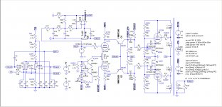
I've added the leakage and capacitance of the transformer using the data shown here: TTG-KT88PP - Tube output transformer [4kOhm] 2xKT88 / 2x300B Push-pull or similar - Shop Toroidy.pl
except the UL connections that are at 23%.
In attachment:
- amended schematic;
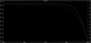
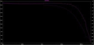
- bode of the amp;
- amended file asc.


THD at 1Wrms still in the ppm range with a DF of 30:
This is the THD at 90 Wrms:
except the UL connections that are at 23%.
In attachment:
- amended schematic;
- bode of the amp;
- amended file asc.
THD at 1Wrms still in the ppm range with a DF of 30:
Code:
Harmonic	Frequency	 Fourier 	Normalized	 Phase  	Normalized
 Number 	  [Hz]   	Component	 Component	[degree]	Phase [deg]
    1   	1.000e+03	4.038e+00	1.000e+00	   -1.19°	    0.00°
    2   	2.000e+03	3.244e-05	8.034e-06	  -86.74°	  -85.55°
    3   	3.000e+03	3.679e-05	9.111e-06	   14.56°	   15.75°
    4   	4.000e+03	5.395e-08	1.336e-08	   -2.13°	   -0.95°
    5   	5.000e+03	3.093e-08	7.660e-09	   -3.31°	   -2.12°
    6   	6.000e+03	4.081e-08	1.011e-08	    3.42°	    4.61°
    7   	7.000e+03	4.198e-08	1.040e-08	   -5.24°	   -4.05°
    8   	8.000e+03	2.990e-08	7.406e-09	    1.19°	    2.38°
    9   	9.000e+03	2.037e-08	5.045e-09	   -4.32°	   -3.14°
Total Harmonic Distortion: 0.001215%(0.000874%)
This is the THD at 90 Wrms:
Code:
Harmonic	Frequency	 Fourier 	Normalized	 Phase  	Normalized
 Number 	  [Hz]   	Component	 Component	[degree]	Phase [deg]
    1   	1.000e+03	3.798e+01	1.000e+00	   -1.21°	    0.00°
    2   	2.000e+03	2.245e-03	5.911e-05	  -89.14°	  -87.93°
    3   	3.000e+03	8.571e-02	2.257e-03	   12.97°	   14.18°
    4   	4.000e+03	5.481e-04	1.443e-05	  -69.38°	  -68.17°
    5   	5.000e+03	3.555e-02	9.361e-04	 -160.31°	 -159.10°
    6   	6.000e+03	5.632e-04	1.483e-05	  116.99°	  118.20°
    7   	7.000e+03	2.246e-02	5.915e-04	   28.03°	   29.24°
    8   	8.000e+03	5.747e-04	1.513e-05	  -59.58°	  -58.37°
    9   	9.000e+03	1.587e-02	4.180e-04	 -145.46°	 -144.25°
Total Harmonic Distortion: 0.254899%(0.268925%)
Attachments
I'm trying to optimize the power supply and power transformer.
For B+ I'mm planning to have a 0-360V 1A secondary, full bridge rectified, then 470uF, then each channel 10 Ohm and another 470uF bypassed by a 4.7u film.
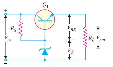
From B+ I'll have a positive voltage regulator down to 280V, and I'm planning to use this: Shunt Regulators
What do you think?
This will be connected to the four 10k of both channels' drivers plate loads, and then each channel independently will set the bias and bjt's base voltages.
Heaters' central tap will be referred to the bottom of the three trimmers through a 10k resistor.
As for the negative voltage of the driver, I'm planning to use a 0-150V 150mA wilding, full bridge rectified and stabilized with the same tubecad's circuit, if approved.
Phase splitter CCS and CorrDiff/ODNF OPAMP will be supplied with a 16-0-16V 150 mA full bridge rectified and stabilized with a pair of 7815 and 7915.
Heaters will be supplied by a 3,15-0-3,15V 10A.
For B+ I'mm planning to have a 0-360V 1A secondary, full bridge rectified, then 470uF, then each channel 10 Ohm and another 470uF bypassed by a 4.7u film.
From B+ I'll have a positive voltage regulator down to 280V, and I'm planning to use this: Shunt Regulators
What do you think?
This will be connected to the four 10k of both channels' drivers plate loads, and then each channel independently will set the bias and bjt's base voltages.
Heaters' central tap will be referred to the bottom of the three trimmers through a 10k resistor.
As for the negative voltage of the driver, I'm planning to use a 0-150V 150mA wilding, full bridge rectified and stabilized with the same tubecad's circuit, if approved.
Phase splitter CCS and CorrDiff/ODNF OPAMP will be supplied with a 16-0-16V 150 mA full bridge rectified and stabilized with a pair of 7815 and 7915.
Heaters will be supplied by a 3,15-0-3,15V 10A.
It might not be a big deal, but high voltage zeners have quite large +tempcos. If you don't mind the zener voltage drifting upwards in voltage a bit then no worries.
Thanks SemperFi,
is this plot reliable?

Are we talking about mV/V per °C? So considering 60°C and 280V, around 15V?
Are there better ways to do it?
Thanks
is this plot reliable?
Are we talking about mV/V per °C? So considering 60°C and 280V, around 15V?
Are there better ways to do it?
Thanks
Last edited:
75V zeners have nearer to 0.1% / °C, and yes the real performance is quite near to the typical data sheet figure.
Test the effect of this on the dc output level.
series-stacked HV zeners can generate a fair bit of noise, too, and I am not convinced that 10µF will do much about it. Still, noise may not matter, for B+.
But the supply-current is essentially stable, both in average and instantaneous terms, so a shunt regulator will not show any advantage over a series regulator in this position, and shunts burn up a large amount of heat that you could do without. for this reason, my new boards have series regulators.
Thank you Rod!
75 mV/°C is something fully manageable. The temperature inside the chassis will be somewhere between 50 and 80°C. Considering 65°C average, that means zeners will be 78V +-1V. That's fine.
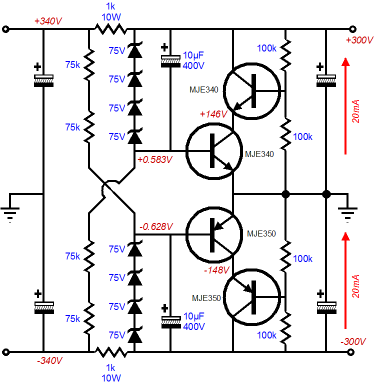
I will use closest values to have around +280 and -160V with a circuit like this that you suggested:
I will update the simulation with the updates, including the power transformer.
75 mV/°C is something fully manageable. The temperature inside the chassis will be somewhere between 50 and 80°C. Considering 65°C average, that means zeners will be 78V +-1V. That's fine.
I will use closest values to have around +280 and -160V with a circuit like this that you suggested:
I will update the simulation with the updates, including the power transformer.
My output transformer is a Toroidy like this one: TTG-KT88PP - Tube output transformer [4kOhm] 2xKT88 / 2x300B Push-pull or similar - Shop Toroidy.pl
but with 23% UL taps.
Based on the data shown on the site I've calculated K as:
Primary Inductance Lp 427 H
Primary Leakage Inductance Lsp 4,58 mH
k = SQRT[(Lp/(Lp + Lr)]
k = SQRT (0,999989274) = 0,999994637
Single winding dc resistance is easy, as it is the full "Total Primary DC Resistance 65,5 Ω" multiplied by the number of turns of each tap (top to bottom): 38,5% 11,5% 11,5% 38,5%.
What it's not clear to me it's how to distribute the "Effective Primary Capacitance 10,5 nF" on all four windings of the primary.
Looking at this document (page 2): http://www.datatronics.com/pdf/distributed_capacitance_paper.pdf
it seems they are proportional to the squared value of the ratio of windings... but if I consider then the primary as four independent winding, the equivalent of the four capacitors in series won't fit the effective primary capacitance of 10,5 nF.
...what am I missing?
Last edited:
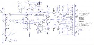
An update on the schematic.
I've split the shunt voltage and bias voltage, so that this schematic can be applied to different drivers, different power tubes and different degrees of local feedback on power tubes.
I've reduced the current through R12 and R20 to minimize the dissipated heat and the voltage margin above and below the needed swing, that now can swing only between -128 and +93V, so maximum 221Vpp (but the power amp reaches its limits when driven at 200Vpp) and this permits to use FQPF9P25 being sure not to exceed its limits.
I know is very unelegant to have a resistor dissipating 11W in heat to supply the driver, but I don't have a dedicated winding on the trafo I have now.
@Rod Coleman:
Do you think I can supply all four bases of the BJTs (considering a stereo amp) with one single supply point and trimmer? Or is it better one trimmer per pair?
This is the simulated result at 100Wrms, with a DF of 2 (Corr.Diff. is disabled by now):
Code:
Harmonic	Frequency	 Fourier 	Normalized	 Phase  	Normalized
 Number 	  [Hz]   	Component	 Component	[degree]	Phase [deg]
    1   	1.000e+03	3.998e+01	1.000e+00	   -1.92°	    0.00°
    2   	2.000e+03	3.141e-02	7.857e-04	  -92.76°	  -90.83°
    3   	3.000e+03	1.200e+00	3.001e-02	    0.88°	    2.80°
    4   	4.000e+03	6.323e-04	1.581e-05	  130.28°	  132.21°
    5   	5.000e+03	4.912e-01	1.228e-02	  177.64°	  179.57°
    6   	6.000e+03	2.565e-04	6.417e-06	   -5.68°	   -3.75°
    7   	7.000e+03	2.531e-01	6.330e-03	   -6.33°	   -4.40°
    8   	8.000e+03	3.165e-04	7.916e-06	  -67.71°	  -65.79°
    9   	9.000e+03	1.221e-01	3.053e-03	  158.31°	  160.23°
Total Harmonic Distortion: 3.318484%(3.327799%)
Attachments

I don't think you need a trimmer for the cascode voltage. It is better to make the tail-current adjustable; you already have a balance adjust pot.
Small voltage changes in the cascode voltage have an effect on the output, so I prefer not to share them between L & R channels.
Small voltage changes in the cascode voltage have an effect on the output, so I prefer not to share them between L & R channels.
Hi Rod,
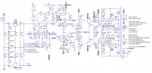
working on your idea of not having a trimmer for the shunt cascode voltage, I've developed this design for the PSU.
D8, Q5, Q7 and R36 create a CCS on R34, R36, R37, R41, so that voltages are kept stable. D1, Q9 and R39 create a CCS for the zener, in order to keep all voltages stable at +-0,5% even with +-10% variation on B+.
The current through R12 and R20 is now kept stable at (R36+R41)*I(R36)/R12. And can be changed by varying R41.
No more need for trimmers except the balance of course.
I've found a better ECC88 working point (on sims) at 108V and 5,3 mA: H3 is worst, but harmonic ratios are way better.
I'm thinking about decoupling the supply ofthe bases of bjts through an RC 10 Ohm and 22uF for each channel, using a single supply point (between R34 and R41) and installing the cap close to bjt's bases.
R37 gives the reference voltage for the heaters.
Is it acceptable?
Attachments


While waiting to have again a space for tests, I've simplified the circuit as follows:

It's a 12AX7 LTP with CCS on the tail, driving a PP of EL84 in UNSET configuration at 19% a-g1 plus 23% a-g2 feedback.
I will try also other percentages of feedback, as previously I tried the same percentage of a-g1and UL feedback with good results.
This configuration gives around 30 Wrms with a DF of 5. Adding the Differential Feedback (to be refined once it will be installed on the real output transformer) the DF goes up to 336.
The idea is to switch the second grid of the LTP to ground or to the Differential Feedback to have two different amps available.
I will start building this very simple amp before going to the previous and more complicated one.
It's a 12AX7 LTP with CCS on the tail, driving a PP of EL84 in UNSET configuration at 19% a-g1 plus 23% a-g2 feedback.
I will try also other percentages of feedback, as previously I tried the same percentage of a-g1and UL feedback with good results.
This configuration gives around 30 Wrms with a DF of 5. Adding the Differential Feedback (to be refined once it will be installed on the real output transformer) the DF goes up to 336.
Code:
Harmonic    Frequency     Fourier     Normalized     Phase      Normalized
 Number       [Hz]       Component     Component    [degree]    Phase [deg]
    1       1.000e+03    2.170e+01    1.000e+00       -0.66°        0.00°
    2       2.000e+03    2.676e-04    1.233e-05      139.55°      140.21°
    3       3.000e+03    2.551e-02    1.176e-03       37.23°       37.89°
    4       4.000e+03    3.714e-04    1.712e-05      -27.15°      -26.49°
    5       5.000e+03    1.854e-02    8.544e-04     -118.59°     -117.92°
    6       6.000e+03    3.311e-04    1.526e-05      167.78°      168.44°
    7       7.000e+03    1.333e-02    6.144e-04       74.04°       74.71°
    8       8.000e+03    2.806e-04    1.293e-05       -1.44°       -0.77°
    9       9.000e+03    7.023e-03    3.237e-04      -84.66°      -84.00°
Total Harmonic Distortion: 0.161117%(0.175237%)
The idea is to switch the second grid of the LTP to ground or to the Differential Feedback to have two different amps available.
I will start building this very simple amp before going to the previous and more complicated one.
Attachments
Differential Feedback apart, has anyone tried something similar?
Will the LPT need a buffer with a ZVN0545A, considering the huge swing needed and the gate capacitance of the FQPF9P25?
Will the LPT need a buffer with a ZVN0545A, considering the huge swing needed and the gate capacitance of the FQPF9P25?
I worked on simplifying the circuit and improve the performance by increasing the current that flows across the phase splitter and increasing its load to 15k, at the same time, with more current available I've been able to lower the load of the shunt cascode phase splitter to 15k while keeping the 230Vpp swing.
I've also implemented a mosfet voltage regulator for shunt's transistor bases, to lower the impedance seen by the bases.

I've reported the wattages dissipated by most critical components.
Do you see any critical point?
I've also implemented a mosfet voltage regulator for shunt's transistor bases, to lower the impedance seen by the bases.
I've reported the wattages dissipated by most critical components.
Do you see any critical point?
The 1W power in the ZTX558 will make them run too hot. 1W is only allowed if the case is at 25 °C. The junction will be at 200 °C! To make the circuit reliable, increase the 15k load resistor for lower idle current, and apply some heatsinking (a bracket to press the two 558s against the chassis).
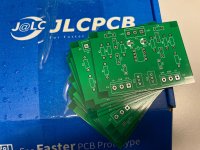
Then, it must be time to build it!
Then, it must be time to build it!
I agree with the idea of building a smaller version of any new and previously unbuilt circuit before building a high power version. EL84's are cheaper than 6550's when something goes wrong. The first UNSETS were built with $1 sweep tubes.It's a 12AX7 LTP with CCS on the tail, driving a PP of EL84 in UNSET configuration at 19% a-g1 plus 23% a-g2 feedback.
I will try also other percentages of feedback, as previously I tried the same percentage of a-g1and UL feedback with good results.
This configuration gives around 30 Wrms with a DF of 5. Adding the Differential Feedback (to be refined once it will be installed on the real output transformer) the DF goes up to 336.
The maximum plate and screen grid spec for the 6BQ5 is 300 volts. The plate rating can be abused liberally, but the screen grid will not like 400 volts in any 6BQ5 / EL84 or Russian variant that I have tried. I did get 30 WPC from some old Sylvania 6BQ5's and also some JJ EL84's over 10 years ago in an SPP board which uses a conventional G1 driven class AB1 design. I ran the plates at 430 volts, but the screens were run around 250 volts with an adjustable mosfet follower circuit. 6BQ5's in UL at much over 300 volts (depending on the tubes used) will not live long. The tubes will cook themselves to death at idle.
Note that some tubes like the 6W6 and it's variants have triode ratings for TV vertical sweep (frame output) that quote a higher screen / plate voltage than the typical screen grid rating for audio use. This rating cannot be used for a typical audio amp unless it is run at full power all the time. The sweep circuits in a TV set never idle, they run at full power forever. Many horizontal (line output) tubes will also die a slow gassy death if their screen grids are run above their spec in triode or otherwise.
Hi, I've tried 27k as load, that should be your value too. Power dissipation reduced to 573 mW, is it still too high for the ZTX558? You use one side grounded, so your dissipation is lower, whilst I need to lower it to -150V to get the right sweep to drive output tubes.To make the circuit reliable, increase the 15k load resistor for lower idle current, and apply some heatsinking (a bracket to press the two 558s against the chassis).
It is indeed, but I just moved to the new house and the music/lab room is still dedicated to other stuffThen, it must be time to build it!
I would also like to find someone capable of correctly layout this amp: the phase splitter has very high gain and I remember you wrote that the layout is critical, and the power amp has input and output in phase, so other issues. I would like to avoid to build an oscillator.
Thanks George, I agree with you, but I admit I'd like to pay the needed to have a pcb to assemble designed by you or Rod.I agree with the idea of building a smaller version of any new and previously unbuilt circuit before building a high power version. EL84's are cheaper than 6550's when something goes wrong. The first UNSETS were built with $1 sweep tubes.
This is indeed why I propose to have the a-g1 feedback equal or similar to the a-g2 (23% each in this case), when the p-mosfet dissipation doesn't become too high: having the a-g1 and a-g2 feedback the same, with the output tube driven from the cathode through the p-mosfet, makes the voltage between g2 and k stable duting the whole period and way lower than B+. With this configuration I have always around 300V between cathode and screen.The maximum plate and screen grid spec for the 6BQ5 is 300 volts. The plate rating can be abused liberally, but the screen grid will not like 400 volts in any 6BQ5 / EL84 or Russian variant that I have tried. 6BQ5's in UL at much over 300 volts (depending on the tubes used) will not live long. The tubes will cook themselves to death at idle.
- Home
- Amplifiers
- Tubes / Valves
- Shunt Cascode Driver meets UNSET for Push-Pull