Voltage feedback is voltage feedback. The main nuance here is what the screen grid is doing for tubes that have one.
Yeap, my comment was precisely to point that out. In absence of CFB can use plate-to-grid. The main point is that classic UL with g2 connected to the OPT is, IME, not not as good as pentode with local fb or modified UL.
What we are discussing here is the opposite: given a certain percentage of plate-g1 feedback, UL in the same percentage gives better performance than pentode.The effect of plate-to-grid fb on the amp performance is pretty much in the same class as CFB. Classic UL and triode benefit at lot less than pentode.
I don't think so. Feedback on g2 is no good. Triode strapped can work ok for several pentodes if efficiency is not important but that doesn't involve the transformer in between the 2 electrodes. It makes a difference for me. That's my opinion, of course. For me the only ultralinear is the modified one with feedback at the cathode and grid not connect to the OPT running with regulated supply.What we are discussing here is the opposite: given a certain percentage of plate-g1 feedback, UL in the same percentage gives better performance than pentode.
Last edited:
I report here some notes that can be useful for the project, taken from Bartola's site here: The Shunt Cascode Driver – Bartola(R) Valves

I will implement this solution as suggested.
A darlington BJT pair instead of Q1 is better because there is effectively no base current error, and the capacitances are lower with BJTs (compared FETs), and the gm higher.
I will implement this solution as suggested.
The limit here should be pmosfet input capacitance, as far as I know. The lower its capacitance, the higher the admissible load resistance, the lower the needed input swing, the lower the distortion.The high R-load works better, because the grid has to swing less for the same output. This reduces triode distortion.
This is what I've already done with the trimmer between cathodes and CCS, with the double purpose of linearising and balancing.A resistor is better in cathode because:
– it degenerates the gm, but linearises it (with zero phase error,unlike loop feedback)
– it holds the anode current steady (important for dc stability)
I don't want to start a debate on coupling caps or to the fact that supply caps are... blabla, but I have to say it is something I consider intriguing. More on that here: https://www.bartola.co.uk/valves/wp-content/uploads/2018/12/DHT-Preamps-ETF2018-final-notes.pdfA DC coupled version can be achieved by placing a gyrator in parallel with RL to set the output voltage to the bias requirements of the output valve and provide a high impedance to let RL set the gain of the shunt cascode driver. This will allow removing the coupling cap (C4 in the diagram above) and provide an end-to-end cap-free system
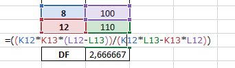
I set the amp at 1 Wrms, then I simulate the output swing on 8 and 12 Ohms, then calculate it through an excel file I did time ago. Do you get different values?
Looking at this datasheet ( https://frank.pocnet.net/sheets/086/k/KT88.pdf ) è see that Pg2 is 6 W and pa+g2 is 40 W. Rg2 is needed to be 1 kOhm instead of 100 Ohm to stay on the safe side.Zintolo - you should check the screen dissipation at higher output levels, looks a bit high!
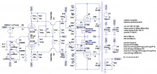
In attachment the schematic with latest upgrades.
The harmonic content seems better with a-g1 exactly the same as UL, indeed.
Seems also the simplest way to keep V(g2,k) constant.

The harmonic content seems better with a-g1 exactly the same as UL, indeed.
Seems also the simplest way to keep V(g2,k) constant.
Attachments

Last edited:
> A darlington BJT pair instead of Q1 is better because there is effectively no base current error, and the capacitances are lower with BJTs (compared FETs), and the gm higher.
Yes, LTSPICE thinks it is better to use a Darlington. But when the circuit meets real life, it is worse.
Notably, the very pleasant and simple cadence of harmonics vanishes, and is replaced by an unstable mix of higher harmonics - in real measurements. Stay with the single PNP!
Yes, LTSPICE thinks it is better to use a Darlington. But when the circuit meets real life, it is worse.
Notably, the very pleasant and simple cadence of harmonics vanishes, and is replaced by an unstable mix of higher harmonics - in real measurements. Stay with the single PNP!
Rod, thank you very much for the hint!
I will try to join your suggestion of the Russian 6Э5П (6E5P) together with SpreadSpectrum suggestion to reach 30% a-g1 feedback with a 100k +100k on top of 100k to ground: 33% a-g1 together with 33%UL.
I remember I cannot drive them properly with ECC88, 6E5P should do it with even lower load resistor, so more bandwidth ( Differential Shunt Cascode Driver ).
...but this only on LTSpice, because I already have two 4KRaa 23% output transformers...
Last edited:
I totally agree with you, but before that I need to overcome some limitations I have:Maybe it's time to stop simulating and start building 😉
- properly layout both the driver due to the very high gain, and the output stage due to the fact that it is a non inverting gain stage (both George and Rod warned about oscillations);
- define all parts more in details to avoid damages;
On the second one I can double check and ask confirmations here.
It would be perfect if someone skilled on the first one would like to do it and then be paid with some fees on a GB for the pcbs, or by a crowdfounding if someone is interested into. George and Rod should already have solved most of the issues.
I'd really like to see this amp come real.
The Shunt Cascode driver will shortly get a 5th revision PCB - the first one since 2016. It will be designed for driving large swings (220V pk-pk) at low distortion.
I can look at how the pair of P-Ch FETs could be driven with one Shunt cascode unit - I don't think a double-unit is necessary. What's the value of Vbias now?
I can look at how the pair of P-Ch FETs could be driven with one Shunt cascode unit - I don't think a double-unit is necessary. What's the value of Vbias now?
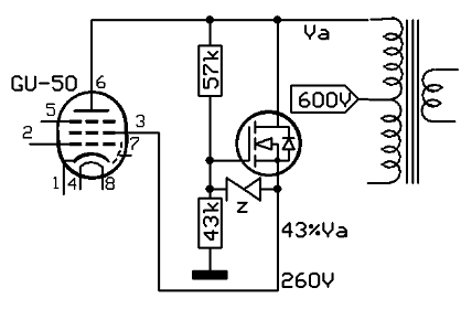
As a reminder and starting point for future implementations, I attach here a schematic Ketje posted years ago to drive g2 without a UL tap (here could be used to experiment different plate-g1 and UL feedback without depending on UL taps).
I set the amp at 1 Wrms, then I simulate the output swing on 8 and 12 Ohms, then calculate it through an excel file I did time ago. Do you get different values?
No, just checking. Yes, Zout is about 2.4 ohms.
I will post the power supply for the stereo version in a dedicated thread:
0-360V 1A for the power tubes (+500V);
0-170V 200mA for the driver (+200V regulated, -240V not regulated) + bias (+140V) + heater reference (+100V);
3.15-0-3.15 9A for the heaters + PI's CCS (-12V through capacitor coupled voltage doubler)
Here it is the version with the protection to the pmosfet.
Am I missing something?

Results at 1 Wrms:
42Wrms:
80 Wrms:
0-360V 1A for the power tubes (+500V);
0-170V 200mA for the driver (+200V regulated, -240V not regulated) + bias (+140V) + heater reference (+100V);
3.15-0-3.15 9A for the heaters + PI's CCS (-12V through capacitor coupled voltage doubler)
Here it is the version with the protection to the pmosfet.
Am I missing something?
Results at 1 Wrms:
Code:
Harmonic	Frequency	 Fourier 	Normalized	 Phase  	Normalized
 Number 	  [Hz]   	Component	 Component	[degree]	Phase [deg]
    1   	1.000e+03	3.921e+00	1.000e+00	   -0.77°	    0.00°
    2   	2.000e+03	2.642e-04	6.737e-05	  -93.89°	  -93.11°
    3   	3.000e+03	3.495e-04	8.913e-05	    2.21°	    2.99°
    4   	4.000e+03	4.938e-06	1.259e-06	  173.87°	  174.64°
    5   	5.000e+03	4.051e-06	1.033e-06	  175.50°	  176.28°
    6   	6.000e+03	3.280e-06	8.365e-07	  175.75°	  176.53°
    7   	7.000e+03	2.812e-06	7.172e-07	  176.39°	  177.16°
    8   	8.000e+03	2.453e-06	6.255e-07	  176.94°	  177.72°
    9   	9.000e+03	2.177e-06	5.552e-07	  177.28°	  178.06°
Total Harmonic Distortion: 0.011174%(0.011144%)
42Wrms:
Code:
Harmonic	Frequency	 Fourier 	Normalized	 Phase  	Normalized
 Number 	  [Hz]   	Component	 Component	[degree]	Phase [deg]
    1   	1.000e+03	2.599e+01	1.000e+00	   -0.80°	    0.00°
    2   	2.000e+03	1.106e-02	4.254e-04	  -92.04°	  -91.24°
    3   	3.000e+03	1.181e-01	4.545e-03	    2.81°	    3.61°
    4   	4.000e+03	1.003e-04	3.858e-06	   99.03°	   99.82°
    5   	5.000e+03	4.331e-03	1.666e-04	 -170.76°	 -169.97°
    6   	6.000e+03	6.877e-05	2.645e-06	  100.98°	  101.78°
    7   	7.000e+03	5.625e-04	2.164e-05	   12.39°	   13.19°
    8   	8.000e+03	3.805e-05	1.464e-06	  103.35°	  104.15°
    9   	9.000e+03	7.935e-05	3.052e-06	  162.45°	  163.25°
Total Harmonic Distortion: 0.456776%(0.456775%)
80 Wrms:
Code:
Harmonic	Frequency	 Fourier 	Normalized	 Phase  	Normalized
 Number 	  [Hz]   	Component	 Component	[degree]	Phase [deg]
    1   	1.000e+03	3.597e+01	1.000e+00	   -0.83°	    0.00°
    2   	2.000e+03	2.179e-02	6.059e-04	  -91.90°	  -91.07°
    3   	3.000e+03	4.654e-01	1.294e-02	    3.22°	    4.06°
    4   	4.000e+03	5.609e-04	1.560e-05	   89.59°	   90.42°
    5   	5.000e+03	7.209e-02	2.004e-03	 -173.66°	 -172.82°
    6   	6.000e+03	1.214e-04	3.375e-06	   99.40°	  100.23°
    7   	7.000e+03	1.778e-02	4.943e-04	    7.09°	    7.92°
    8   	8.000e+03	7.186e-05	1.998e-06	   92.02°	   92.85°
    9   	9.000e+03	3.179e-03	8.839e-05	 -170.70°	 -169.87°
Total Harmonic Distortion: 1.311753%(1.311753%)
Attachments
To test Zout, I like to try to drive the output of the amplifier from an AC source with a resistor in series. I put together a higher-current op amp follower with a 50 Ohm resistor on its output. Then I drive the amplifier output with a sine wave and solve for the unknown resistance.
I once ran through the calculations in RDH4 to estimate the Zout of a pentode output stage with feedback and if I remember correctly the connected load appears as a term in that calculation. So the Zout varies as the load varies. I don't that term was very large compared to the others, but it would be especially easy to use this method in a simulation.
2.4 Ohms seems low for a 4k transformer but maybe your toroid just has low winding resistances compared to the Hammond 1650R. My Plitron toroid transformer is that way. With 50% feedback (Unity-Coupled configuration) I get 1.1 Ohm Zout without any global feedback. 80 Ohm primary and 0.18 Ohm secondary for that transformer.
- Home
- Amplifiers
- Tubes / Valves
- Shunt Cascode Driver meets UNSET for Push-Pull