That was one of the thing I would have simulated tonight. Thanks for your suggestion!If the Shunt Cascode's current source is replaced by resistors, the power supply rejection is poor like this. To get the performance back to the level with a current source, a regulated supply must be used. Much more complicated than a current source.
I'm very proud to have both you Rod and George writing on this thread.
One thing I don't like...
If the Shunt Cascode's current source is replaced by resistors [R12, R20 in this case] the performance is degraded. It's because the power supply rejection is poor like this. To get the performance back to the level with a current source, a regulated supply must be used. Much more complicated than a current source.
Agree entirely for an SE amp. But I had a regulated supply available anyway. If the cascode reference voltage is derived with a divider from the same B+ that is supplying the anode resistors, and you bypass the divider output with a capacitor to B+ rather than ground, the PSRR is quite good. Any residual noise from the power suppy that finds it way to the output of the shunt cascode is common mode so is rejected in a push-pull output stage. Just trying to keep things simple.
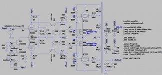
I attach here the updated schematic with resistor loaded LTPI (but still CCS on the cathode). Performance is a little bit worst with such a low load, but almost unchanged with 10k and 200V lost on those resistors.
1k is definitely too low, I used 2.7k from a regulated rail that was about 18V higher than the anode voltage. Obviously higher is better. CCS is ideal but you need 4 of them for stereo and have to adjust all of them. If you have a nice pcb with all that on there that's great but I was doing it on the cheap with veroboard and P2P.
Why is PSRR an issue? This is a differential stage and the ripple is common mode.
And why does the anode load resistor have to be so small? Why can't you make it a lot larger and feed it from a much higher B+?
And why does the anode load resistor have to be so small? Why can't you make it a lot larger and feed it from a much higher B+?
Thanks, that reminds me of my readings on tubecad.com and I will try to inject noise to see how it will react.If the cascode reference voltage is derived with a divider from the same B+ that is supplying the anode resistors, and you bypass the divider output with a capacitor to B+ rather than ground, the PSRR is quite good. Just trying to keep things simple.
I will check a reasonable voltage for the PI, also considering I would like to simplify the power supply as well. Having around +140V bias voltage for the PMOSFET, and -200V as reference voltage for the 27 kOhm load resistors, a +-200V could be a good starting point.
So the voltage divider could be 560k on 470k (that gives 91V) with 100n in parallel with 560k.
5.6 kOhm load for the PI will guarantee (200-91)/5.6k = 19.5 mA
It will dissipate 2.2 W, so a 5W resistor is needed.
Then I need to set the PI's tail CCS to center the working point of the stage between -200 V and +90V, so around -55V, that means 2mA on 27 kOhm with no signal, so the CCS must be set at 19.5 x 2 - 2 x 2 = 35 mA.
The 27k load resistor will dissipate 100 mW, so a 1W resistor is enough.
Thanks, I will try different options, +-200Vdc supply could be an easy solution together with +500V for the plates, to simplify the PSU.1k is definitely too low, I used 2.7k from a regulated rail that was about 18V higher than the anode voltage. Obviously higher is better.
I need to do something similar, I have no competences to design a pcb for an amp that has such gain and no phase inversion, without having oscillations.I was doing it on the cheap with veroboard and P2P.
First test I did was with 10k and there was no performance degradation but I'd dissipatw 8 W per channel; with 1k there was performance degradation indeed. 5k6 seems a good compromise.Why can't you make it a lot larger and feed it from a much higher B+?
I think a dedicated 150-0-150 Vac could be a good starting point, because it will supply CCS loads, and PSU should be quite stable. Do you agree?1k is definitely too low, I used 2.7k from a regulated rail that was about 18V higher than the anode voltage.
This is the schematic I will simulate injecting noise on different parts of the PSU.

PT could have only three secondaries:
0-360V plus 0-150V plus 3.15-0-3.15V
...but I have to say that I don't like to dissipate that much on R22, most probably another supply just for the CCS would be better also on the thermal point of view.
Performance is unaltered, same as before up to 80 Wrms.
PT could have only three secondaries:
0-360V plus 0-150V plus 3.15-0-3.15V
...but I have to say that I don't like to dissipate that much on R22, most probably another supply just for the CCS would be better also on the thermal point of view.
Performance is unaltered, same as before up to 80 Wrms.
Attachments
Last edited:
Zintolo, can you post the models for your solid state devices or links to them? I'd like to sim this circuit and try a few things but I don't have the models you're using. Thanks
Hi dgta,
I've just used the SS devices already available on LTSpice (plus notes on what to use in reality). Have you updated it recently? It should update SS models as well.
If not, I will search through my models and post them.
I've just used the SS devices already available on LTSpice (plus notes on what to use in reality). Have you updated it recently? It should update SS models as well.
If not, I will search through my models and post them.
Well, I just updated today and it can't find the DN2540, the 2SA transistor and of course the LedRed. So I don't think those are in the included library. Please post those or a link to them. Thanks.
Actually 29 mA, it needs to be just right to get maximum swing. R12 current is 19.7 mA, anode current 14.5 mA leaving 5.2 mA through R21, with voltage on Q1 collector of -59.
...but I have to say that I don't like to dissipate that much on R22, most probably another supply just for the CCS would be better also on the thermal point of view.
You could derive a -12V supply (which is all you need) by capacitor coupling a voltage doubler to the heater supply, then get rid of R22 altogether.
I had a few thoughts:
1. I made the curves posted above by following the procedure in O.H. Schade's paper. They are calculated, not measured.
2. I think that you will get better results if you don't do the UL for the screens. Remember that UL is just a compromise between triode connection and pentode connection. To get behavior like the magenta curves above, you need full pentode connection. UL will give you curve shapes that are somewhere between the light blue curves and the magenta curves, which I would expect to make them worse.
UL never made sense to me as an optimal solution. You take a nonlinearity that originated in the g1-plate characteristic and you apply a correction to g2, which has completely different characteristics, so the distortion correction isn't as good as it would be as if you applied that same amount of feedback to g1.
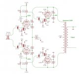
3. A while back I drew up a plan for a push-pull experiment combining the Corona input stage with something similar to the UNSET output stage. I haven't built this yet, but I've attached it here in case there is anything of interest to you in it.
I like the idea of a cascode providing high gain in an input stage rather than a pentode. Maybe it offers some noise performance benefits?
1. I made the curves posted above by following the procedure in O.H. Schade's paper. They are calculated, not measured.
2. I think that you will get better results if you don't do the UL for the screens. Remember that UL is just a compromise between triode connection and pentode connection. To get behavior like the magenta curves above, you need full pentode connection. UL will give you curve shapes that are somewhere between the light blue curves and the magenta curves, which I would expect to make them worse.
UL never made sense to me as an optimal solution. You take a nonlinearity that originated in the g1-plate characteristic and you apply a correction to g2, which has completely different characteristics, so the distortion correction isn't as good as it would be as if you applied that same amount of feedback to g1.
3. A while back I drew up a plan for a push-pull experiment combining the Corona input stage with something similar to the UNSET output stage. I haven't built this yet, but I've attached it here in case there is anything of interest to you in it.
I like the idea of a cascode providing high gain in an input stage rather than a pentode. Maybe it offers some noise performance benefits?
Attachments
I was thinking the same thing with the ultralinear connection. But according to the Spice model, distortion is halved with the ultralinear connection. Output impedance is much the same with or without.
That's interesting.
It wouldn't be the first time I'd seen something made "worse" that actually gave better system-level performance.
I'd also be cautious that the simulation might not match reality. I'd recommend trying it both ways in an actual circuit to see if this effect pans out in the real world.
It wouldn't be the first time I'd seen something made "worse" that actually gave better system-level performance.
I'd also be cautious that the simulation might not match reality. I'd recommend trying it both ways in an actual circuit to see if this effect pans out in the real world.
- Home
- Amplifiers
- Tubes / Valves
- Shunt Cascode Driver meets UNSET for Push-Pull