Thanks for the idea!You could derive a -12V supply (which is all you need) by capacitor coupling a voltage doubler to the heater supply, then get rid of R22 altogether.
I did several simulations, and best results happened with almost the same percentage of UL and plate-g1 feedback, with an acceptable DF of 3.52. I think that you will get better results if you don't do the UL for the screens.
I remember that thread ( If UNSET and the RCA50W Had a Baby ) and it is very interesting, but I would avoid the input transformer.3. A while back I drew up a plan for a push-pull experiment combining the Corona input stage with something similar to the UNSET output stage. I haven't built this yet, but I've attached it here in case there is anything of interest to you in it.
I still have to perform those tests, I will during the weekend.I like the idea of a cascode providing high gain in an input stage rather than a pentode. Maybe it offers some noise performance benefits?
it is very interesting, but I would avoid the input transformer.
Since the input impedance to the mosfet under the cathode on the driver tube is very high and constant, I use a simple split load PI, often made with a mosfet.
I have also experimented with CCS and "gyrator" loads on the pentode to increase the gain and drive current into the fat mosfet under the output tube cathode. As I have been told a few times, it does swing close to saturation which causes it's capacitances to change a lot during a drive cycle.
I've just found the Jensen transformer to be quite good and I like the galvanic isolation. It's not necessary but my current setup can't be quieted completely without it. I'd rather have tiny distortion added than tiny buzz.
I also had to include an optical USB isolator into the setup or I'd get strange sounds coupling into the ground from the computer. Adding the isolator between the computer and the USB soundcard made the sounds go away.
I also had to include an optical USB isolator into the setup or I'd get strange sounds coupling into the ground from the computer. Adding the isolator between the computer and the USB soundcard made the sounds go away.
Ok, I had a chance to play with the circuit a bit. Very nice. It works as advertised, which is to say very well. The driver delivers somewhere around 120Vp of swing per side, at low distortion. It certainly is a clever circuit. Not to detract from its cleverness, but I was able to do the same with a conventional all-tube design involving no cascodes.
The UNSET/UL power stage is certainly worth a lot of discussion, very interesting subject. When driving the cathode, seems to me there is screen feedback in pentode, as the instantaneous voltage at the cathode varies with respect to g2. So by applying g2 FB via UL, you're partially cancelling that. No?
The UNSET/UL power stage is certainly worth a lot of discussion, very interesting subject. When driving the cathode, seems to me there is screen feedback in pentode, as the instantaneous voltage at the cathode varies with respect to g2. So by applying g2 FB via UL, you're partially cancelling that. No?
Yeah, cathode drive AC voltage is also impressed on the screen (with respect to cathode) if the screen is held at constant voltage (with respect to gnd).
UL will be the a fraction of plate swing applied to the screen in opposite direction. Plate swing has some distortion added. Lower distortion would probably occur if you could just keep Vg2-k totally constant, but this UL might be doing a pretty good job and it is dead simple.
UL will be the a fraction of plate swing applied to the screen in opposite direction. Plate swing has some distortion added. Lower distortion would probably occur if you could just keep Vg2-k totally constant, but this UL might be doing a pretty good job and it is dead simple.
Yes. What we have here is a circuit where all elements except the anode are driven.
I think George was saying the cathode drive is similar to dual drive in the sense that you're varying both Vgk and Vg2-k at the same time. Once you add the a-g feedback and the UL, things get a little more complex. As a rough approximation, I'd say the a-g feedback could linearize the g1 curve and the UL could linearize the g2 curve.
I think George was saying the cathode drive is similar to dual drive in the sense that you're varying both Vgk and Vg2-k at the same time. Once you add the a-g feedback and the UL, things get a little more complex. As a rough approximation, I'd say the a-g feedback could linearize the g1 curve and the UL could linearize the g2 curve.
This is another solution I though but not simulated yet: a single shunt cascoded amplification stage followed by a mosfet driver. But I have to say I prefer the actual one.I use a simple split load PI, often made with a mosfet.
May ask why you have two pmosfets in parallel on the cathode of the power tubes? Should I foresee the same here?
Totally agree, in my case I would keep the amp simple and possibly economic as well.I'd rather have tiny distortion added than tiny buzz.
I've often had that kind of issues, I've bought a bluetooth DAC to see how it performs. It could become part of this amp. The clever thing is that automatically switches from RCAs to bluetooth when you connect to it.Adding the isolator between the computer and the USB soundcard made the sounds go away.
UL will be the a fraction of plate swing applied to the screen in opposite direction. Plate swing has some distortion added. Lower distortion would probably occur if you could just keep Vg2-k totally constant, but this UL might be doing a pretty good job and it is dead simple.
Yes. What we have here is a circuit where all elements except the anode are driven.
As a rough approximation, I'd say the a-g feedback could linearize the g1 curve and the UL could linearize the g2 curve.
Thank you guys, I've just found that almost the same amount of p-g1 and UL gives very good results with a simple circuit, but I wasn't able to explain why. Now I start to understand.
Yes, that was a good observation. Seems that performance is optimised when V(g2,K) stays about constant. In this circuit just a slightly higher UL ratio does that.
Zintolo - you should check the screen dissipation at higher output levels, looks a bit high!
Zintolo - you should check the screen dissipation at higher output levels, looks a bit high!
This reminds me Wavebourn suggesting to keep V(g2-k) constant with a low impedance connection. It should be a GU-50 thread IIRC. What about supplying g2 with a dropping resistor and a zener referred to the cathode, instead of UL? It will make the output transformer cheaper, so the overall project even cheaper and most of all it will free the choice of the plate-g1 feedback, instead of obliging to use the same as UL taps.Yes, that was a good observation. Seems that performance is optimised when V(g2,K) stays about constant. In this circuit just a slightly higher UL ratio does that.
Thanks for it! I didn't notice before.Zintolo - you should check the screen dissipation at higher output levels, looks a bit high!
With standard output stage, I have completely forgotten about the classic UL.
The pentode stage with 10%-20% max cathode feedback is more efficient than the classic 43% UL and performs better without stressing the tubes which the UL does with g2 attached to the OPT .
In reality a pentode with cathode feedback without an AC reference between g2 and cathode is virtually an UL but in practice it's a totally different animal respect to the standard UL.
This was named modified UL by Crowhurst. In fact if the partition is the same the output power is the same but the distortion is much lower for the modified UL: 5-10 times lower at any output level.
The effect of plate-to-grid fb on the amp performance is pretty much in the same class as CFB. Classic UL and triode benefit at lot less than pentode.
I would not believe simulations when it comes down to distortion figures.
Last edited:
Yes. What we have here is a circuit where all elements except the anode are driven.
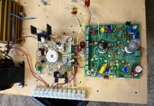
I created a push pull driver board in 2015 from the design work I did in this long thread from 2008. There are plenty of details there for those with plenty of time. The new driver is much like the 2008 version except for the tube sizes. It can output both polarity drive signals with a variable DC offset (bias) that can be positive (screen drive) or negative (G1 drive).
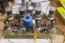
6L6GC AB2 Amp
I then created a pair of prototype boards with a mosfet tied to each pin of the tube except for the heater and plate. Both P and N channel fets were tried for sourcing current, and sinking current, with variable AC drive or either phase.
These pictures are from 2016. I played with these boards and LT spice off and on for a couple of years before making the first successful amp in 2018, a push pull design with small 6GF5 sweep tubes.
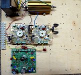
May ask why you have two pmosfets in parallel on the cathode of the power tubes?
The schematic shown is for the PC board layout. In order to accommodate both top of board and bottom of board population two mosfets must be placed in the schematic. Only ONE is placed on the board at build time. Same with the screen regulator N fet.
Attachments
I'm thinking that I most probably adopt the resistor load instead of CCS load for the triode, also because a stabilized supply for bot positive and negative rail (for the PI only) will optimize the available swing also in case of voltage fluctuations.
I haven't found that post, but this one instead: different thing, but it is another option to try Advanced CFB questions, limited power.This reminds me Wavebourn suggesting to keep V(g2-k) constant with a low impedance connection.
Thanks again George! I will probably ask you some more questions about the specific SS devices and their protection.Only ONE is placed on the board at build time. Same with the screen regulator N fet.
Since the input impedance to the mosfet under the cathode on the driver tube is very high and constant, I use a simple split load PI, often made with a mosfet.
The cathode drive has the great benefit of high input Z. So easy on the driver. But his circuit requires a swing of 120Vp (240Vpp) each side, so a concertina may be a little awkward.
The effect of plate-to-grid fb on the amp performance is pretty much in the same class as CFB. Classic UL and triode benefit at lot less than pentode.
Voltage feedback is voltage feedback. The main nuance here is what the screen grid is doing for tubes that have one.
Oh, and another point for Zintolo, I have plate-grid feedback KT88 measured results for Zout with a Hammond 1650R and 20% feedback of 3.3 Ohms on the 8 Ohm tap, running them at 60mA. I bumped the feedback up to 30% and got Zout down to 2.4 Ohms.
More info here if you are interested.
Here is a post with results from some experiments I did some years ago to generate very large swings at ultra-low distortion.
I did some simulations with 30% plate-g1 plus 30% UL, but the bottleneck was the required driving swing: the PI was distorting way before KT88s.I have plate-grid feedback KT88 measured results for Zout with a Hammond 1650R and 20% feedback of 3.3 Ohms on the 8 Ohm tap, running them at 60mA. I bumped the feedback up to 30% and got Zout down to 2.4 Ohms.
More info here if you are interested.
Thanks, I missed this page of yours!Here is a post with results from some experiments I did some years ago to generate very large swings at ultra-low distortion.
I have two Toroidy PP 4k Raa output transformers with custom 23% UL taps. Starting from the data shown on their site for the stock 40% UL version, I scaled the total Rdc to the new taps and simulated it.What OPT did you sim and what is the nominal primary Zaa?
Last edited:
- Home
- Amplifiers
- Tubes / Valves
- Shunt Cascode Driver meets UNSET for Push-Pull