Pictures
Thank you for the fast response, I appreciate it very much.
Here are pictures from all cables and as you can see I have taken away the heat shrink sleaves to check cable separation and continuity and they are just fine.


Thank you for the fast response, I appreciate it very much.
Here are pictures from all cables and as you can see I have taken away the heat shrink sleaves to check cable separation and continuity and they are just fine.
TIC37,
Thank you for your pictures !
Due to the way you have arranged the mechanic and Shiga MKII, the ribbon optical cable is reversed.
You need to place mechanic such way that connection is like in the picture from my website.
Regards,
Tibi
Thank you for your pictures !
Due to the way you have arranged the mechanic and Shiga MKII, the ribbon optical cable is reversed.
You need to place mechanic such way that connection is like in the picture from my website.
An externally hosted image should be here but it was not working when we last tested it.
Regards,
Tibi
Playing
After some rearangements on the board we are good!
Me like! From cold start it is way better than my PS1 cd player with Salas shunts. Better resolution, 3 D stage, bass whatever you want to compare it is way better and still, my PS1 cd player wipes the floor with many good cd players already.
Now it is on repeat for some days and then I will start making it betterb if that is possible but appearantly it is doable according to this thread.

Hi Tibi,
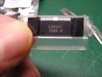
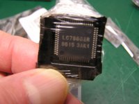
All new connectors and cables did not change anything so I am committing to changing IC's. I bought the pictured IC's when I originally purchased shiga because I was not sure of my soldering skills. I ended up waiting and getting the soldering experience but looks like I still will need. Do these IC's look right for replacement. Thanks!
best regards,
Steve
Attachments


Hello Tibi,
First of all I feel sorry for you for the loss of your good friend. Please keep him in good memory!
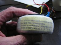
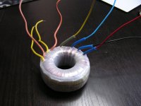
The transformer you send me recently acts wierd. Refurring to your picture (see attachtsment) I have to use other wires to make it work. I have to connect the two 220Vac and use brown and black for current to make it work. Doing so the PSU lights up. Did not dare to connect it to the board. I used my old transformer and wired it as shown on the picture and everything works fine, but the backlight of the LCD stays dark. What is wrong?
Regards,
Robert
Steve,
Please check if LC78601 oscillator is working.
Chips looks good. Replace first LA9242.
Regards,
Tibi
Please check if LC78601 oscillator is working.
Chips looks good. Replace first LA9242.
Regards,
Tibi
Hello Robert,
Thank you ! Please post a picture with your transformer paper stick. I had several types. The one in picture is 2 x 9V, while latest is 2 x 10V.
Regards,
Tibi
Thank you ! Please post a picture with your transformer paper stick. I had several types. The one in picture is 2 x 9V, while latest is 2 x 10V.
Regards,
Tibi
Hello Robert,
For 220V you need to connect red and blue.
For 110V you need to connect red and black.
Backlight have nothing to do with trafo. Backlight have pins made from pcb, sometimes this do not solder properly. Please check and resolder.
Regards,
Tibi
For 220V you need to connect red and blue.
For 110V you need to connect red and black.
Backlight have nothing to do with trafo. Backlight have pins made from pcb, sometimes this do not solder properly. Please check and resolder.
Regards,
Tibi
Hi Tibi,
I know backlight has nothing to do with trafo, but I wanted to raise two questions in one massage.
In the Netherlands current is 220/230V. When I connect red and blue as you recomment, nothing happens. Using my old trafo connected as the picture attached to my massage on page 172, it works well.
?????
PSU
I have a question about the LDO regulator for the PSU.
I see that it is surgested LT1086 but I have 1085 at home so the question is are they comparable??
Seem that the only difference is the amount of drop out voltage where 1086 have 1.2 volt drop out while 1085 have 1.3 volt drop out.
I have a question about the LDO regulator for the PSU.
I see that it is surgested LT1086 but I have 1085 at home so the question is are they comparable??
Seem that the only difference is the amount of drop out voltage where 1086 have 1.2 volt drop out while 1085 have 1.3 volt drop out.
Hi Tibi,
I need help in how to test LC78601 oscillator. I have a basic understanding of VCO's/PLL's. I see pins 3-7 are PLL circuit, pin 11 is test mode TMOD and pin50 FSX is test output [7.35kHz test mode or low output normal]. 60/61 are external clock. I don't know where to go from there. Do I need to analyze PLL or just look for a VCO output. Which pins? Or am I just looking for a signal at its destination from oscillator? If this inquiry is beyond this forum I apologize. Thanks for any help.
regards,
Steve
Robert,
Please check primary continuity between wires and secondary as well. These are factory tested transformers and when properly used are 100% working proof. Maybe one primary wire was broken due some stress.You may check up to where the connection is done with CuEm wire winding start.
Regards,
Tibi
Please check primary continuity between wires and secondary as well. These are factory tested transformers and when properly used are 100% working proof. Maybe one primary wire was broken due some stress.You may check up to where the connection is done with CuEm wire winding start.
Regards,
Tibi
I have a question about the LDO regulator for the PSU.
I see that it is surgested LT1086 but I have 1085 at home so the question is are they comparable??
Seem that the only difference is the amount of drop out voltage where 1086 have 1.2 volt drop out while 1085 have 1.3 volt drop out.
Reference voltage is same 1,25V on both LT1085 and LT1086. You may use 1085 instead 1086. Please keep drop out voltage above 3V for good regulation.
Regards,
Tibi
Hi Steve,
You may check if LC78601 oscillator still work by connecting your scope on pin 60 or over capacitor C58. If you see a deformed square signal (due oscilloscope input capacitance) at 16,9344MHz, than LC78601 may still work and you need to proceed replacing LA9242. LA6541 may work up to 12V, so this is not be replaced.
Regards,
Tibi
- Home
- Source & Line
- Digital Source
- Shigaclone MKII Black - The builders Thread