 New LA6541 now has NO response to anything. No LED display no motor overdrive, not even the wrong response 😕 Bogus part maybe 😡 What to do next
  ? I just can't see what I have done wrong 🙁 ! TAKING A BREAK for today.
Steve
Steve,
I have corrected your doc as here below.
Please note that regulators can be used on V1,V2,V3,V4 independently. For example, if you want to use regulator only in V3 position, than remove only L5 ferrite bead. For V4 remove only L9 ferrite bead and so on.
It is important that V1=V2=V3=V4=5V within 100mV, variation +/-50mV
Measure your regulator before connecting to main board and keep one single ground point at J6 connector if possible.
Regards,
Tibi
Reflektor D or LT1086-5
V1 ATTENTION remove L2 ferrite bead before using separate power supply for this section.
Trough V1 following sections will be powered:
- LA9242M Vcc1 pin 64 for ASP radio frequency section
- Vcc for laser CCS (constant current source)
- Vcc for PIN photo detector (mechanic optical)
Mini-reg
V2 ATTENTION remove L3 ferrite bead before using separate power supply for this section.
Trough V2 following sections will be powered:
- LA9242M Vcc2 pin 56 for servo system and digital system
Reflektor D or Mini-reg
V3 ATTENTION remove L5 ferrite bead before using separate power supply for this section.
Trough V3 following sections will be powered:
- LC78601 VVdd pin 6 for internal VCO power supply
- LC78601 Xvdd pin 62 for internal crystal oscillator circuit power supply
Mini-reg
V4 ATTENTION remove L9 bead before using separate power supply for this section.
Trough V4 following sections will be powered:
- LC78601 Vdd pin 22 for digital system power supply
- LC78601 VLCD1 pin 40 for LCD drive bias 1/2 VDD monitor
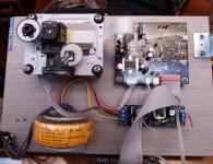
Hi Tibi,
I had to re-solder L8 and now I am back to where I started. XO out at pin 60 is giving me a triangle waveform not a flat top square wave. All power supplies check out 5.0 to 5.1 V at appropriate pins.
regards,
Steve
PS maybe a deformed square as it is not a perfect triangle [camera battery dead right now]
Last edited:
Hi Tibi,
I had been using the wiring diagram attached from MKII. I matched J6 Motor pinout matching 1-6 to 1-6 on sled. Unfortunately this was backwards,
PUIN and Gnd was going to spindle motor. So I reversed now[J6 1 to Pin 6 CD deck etc.] and spindle motor activates, laser head motor moves, TOC activates with laser trying to read but it does not happen. Eventually it stops, I can press CD door again and it repeats the sequence. I am using a stock transport, no mods, solidly mounted and contact clean/lubrication on ribbon cable. What should I check next? Thanks!
best regards,
Steve
Attachments
While I am still waiting for my MK II board to come, I followed some of the MK II changes to apply them to the MK I board. Since then, it never failed to read TOC even I tested with CDR. The only moment that it stopped working was when I put a new mechanism in (old one was going through the mech mods) and forgot to remove the protection blob. Your symptom sounded like the protection blob is still intact in the mech.
Another occasion that I ran into this symptom was I lifted the trace (and didn't know) while replacing caps. This can be a possibility as you replaced the chips and might introduce bad contact. Unfortunately, this kind of problem can be very difficult to track.
BTW, the mechanism mods is a must. Consider this, I only did the mods using the parts that I had in possession, not exactly the parts as Tibi suggested. Besides soldering the MKP1837 to the diode, everything else was unnamed low ESR polyester 0.1uF caps. The improvement is still tremendous. No cap change to the MK I board had this kind of impact. I will rate this as the number 1 mod before everything else.
Hi Tibi,
I had been using the wiring diagram attached from MKII. I matched J6 Motor pinout matching 1-6 to 1-6 on sled. Unfortunately this was backwards,
PUIN and Gnd was going to spindle motor. So I reversed now[J6 1 to Pin 6 CD deck etc.] and spindle motor activates, laser head motor moves, TOC activates with laser trying to read but it does not happen. Eventually it stops, I can press CD door again and it repeats the sequence. I am using a stock transport, no mods, solidly mounted and contact clean/lubrication on ribbon cable. What should I check next? Thanks!
best regards,
Steve
Hi Steve,
I need a more clear picture on what are you doing. It is a Shiga MKII or Shiga MKI ? It this one purchased mounted and tested by me ?
It is a new CD mechanic ? Have you removed laser protection solder bulb ?
How is this mounted on solid wood ? It is the ribbon cable straight ?
Please provide some pictures.
Regards,
Tibi
Hi Tibi,
It is the kit so I have done all the build. MKII Black. I am using my unmodified CD mechanic while troubleshooting. Solder blob is removed. Straight line ribbon cable. Laser is performing all functions. Laser searches in all planes and is on. TOC switch activates search. Display DOES NOT change, only displays 88 with Play, Repeat, Memory. I am waiting for a micro clip for my scope so I can check digital IC signals as analog [servos] appear to be functioning. Using Tentlab clock and appears to be working. I posted images several days back. I don't know if photo diodes are why tracking fails or the signals are not reaching IC's for processing, or not getting through after making it to IC's. My first idea was to try to find a way to check photo diodes functioning and then move to IC's. I use textbooks and online resources to teach myself as I go. I am a true amateur but I really enjoy this and this project is really pushing my learning curve. So my challenges are my own making and not an indication of any problem with your player! If I get close to the results posted by others it will be totally worth it! Thanks for all your help.
best regards,
Steve
... Display DOES NOT change, only displays 88 with Play, Repeat, Memory. ...
Hi Steve,
Display should indicate -- while reading TOC and if not successful 00, not 88 all the time.
This clearly indicate that LC78601 is improper soldered, or have some pin shortcuts. Take a good lens magnifier and look closely on each pin, see if it make solder contact with PCB. Measure continuity on adjacent pins with a multimeter. If there is continuity, there is a good change that you have a shortcut.
Brgds,
Tibi

Hi Tibi,
I have flashing -- while searching then 00 and stops. I have 3 different ribbon cables all new including yours. Is it safe to spray electronic component cleaner/lubricant into the 16 pin connector on the laser unit? The laser drive motor seems to be searching correctly as it stays within the CD size. The laser optics move up and down for focus. The spindle motor activates and changes speed correctly. I am able to detect red not white light through phone camera lens[cheap phone] during search/focus activity. As I stated before I have no solder bridges detectable or visualized. Tkanks again!
regards,
Steve
Spray cleaner lubricant on 16 pin ribbon cable and remove excess with a napkin.
You may have a mechanic with PIN diode problem or distance between turntable and laser was affected - see mechanic datasheet - https://vicol-audio.com/docs/DA11VZ.pdf
Change mechanic if you have a spare one.
BTW, have you measured each smd part before mounting ?
Regards,
Tibi
You may have a mechanic with PIN diode problem or distance between turntable and laser was affected - see mechanic datasheet - https://vicol-audio.com/docs/DA11VZ.pdf
Change mechanic if you have a spare one.
BTW, have you measured each smd part before mounting ?
Regards,
Tibi
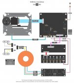
Hi Tibi and the community,
Got the kit for quite a while. Decided to put it together just recently.
And my black shigaclone doesn't work properly after finishing all the soldering.
So here I am. XD
Here is what I've got:
1. The backlight doesn't go on.
2. Missing digits on the LCD.
3. If the ribbon cable from the laser module to the main board being connected, the LCD doesn't show and the motor won't spin. But if disconnected the ribbon cable, the motor spins and the keys seems to be functional.
The output voltage from the regulator board is 7.95V. V1 is only about 350mv. (Is V1 a point of J12 with a white square mark above it?) The voltage of V2,V3,V4 is similar.
Check the threads and don't know which point to start trouble shooing with.
I attached some photos and a movie clip. Please kindly shed some light.
Thanks,
Lee
YouTube
Got the kit for quite a while. Decided to put it together just recently.
And my black shigaclone doesn't work properly after finishing all the soldering.
So here I am. XD
Here is what I've got:
1. The backlight doesn't go on.
2. Missing digits on the LCD.
3. If the ribbon cable from the laser module to the main board being connected, the LCD doesn't show and the motor won't spin. But if disconnected the ribbon cable, the motor spins and the keys seems to be functional.
The output voltage from the regulator board is 7.95V. V1 is only about 350mv. (Is V1 a point of J12 with a white square mark above it?) The voltage of V2,V3,V4 is similar.
Check the threads and don't know which point to start trouble shooing with.
I attached some photos and a movie clip. Please kindly shed some light.
Thanks,
Lee
An externally hosted image should be here but it was not working when we last tested it.
An externally hosted image should be here but it was not working when we last tested it.
An externally hosted image should be here but it was not working when we last tested it.
YouTube
Last edited:

Hi Tibi,
No I did not measure every smd before. I am starting today to go part by part for values and assess all connections. I have tried different mech but not recently, will revisit.
thanks again,
Steve
No I did not measure every smd before. I am starting today to go part by part for values and assess all connections. I have tried different mech but not recently, will revisit.
thanks again,
Steve
Hey there.
Hey making an original Shigaclone for my brother from parts out of the parts box. Having fun.
Just did the laser mods. I had forgotten what an incredible difference those caps make (also what a pain in the a@@e it is to implement!)
I got some spare lasers that have both a cap and a resistor next to the laser pins. Can you please remind me - do they both come off or just the cap?
Thanks
Hi Tibi and the community,
Got the kit for quite a while. Decided to put it together just recently.
And my black shigaclone doesn't work properly after finishing all the soldering.
So here I am. XD
Here is what I've got:
1. The backlight doesn't go on.
2. Missing digits on the LCD.
3. If the ribbon cable from the laser module to the main board being connected, the LCD doesn't show and the motor won't spin. But if disconnected the ribbon cable, the motor spins and the keys seems to be functional.
The output voltage from the regulator board is 7.95V. V1 is only about 350mv. (Is V1 a point of J12 with a white square mark above it?) The voltage of V2,V3,V4 is similar.
Check the threads and don't know which point to start trouble shooing with.
I attached some photos and a movie clip. Please kindly shed some light.
Thanks,
Lee
Lee,
You should measure 5V at V1, V2, V3 and V4 square point. Try to resolder backlight, but will not work witout 5V at mentioned V1-V4 points.
Please check also if you removed solder protection bulb for laser.
Missing digits may be due flat cable was twisted too hard. Check continuity or press connectors.
Regards,
Tibi
...
I got some spare lasers that have both a cap and a resistor next to the laser pins. Can you please remind me - do they both come off or just the cap?
Thanks
There is no resistor near laser. Only an 100nF cap that must be removed and changed with 1nF silver-mica across a 100nF Vishay.
Regards,
Tibi
There is no resistor near laser. Only an 100nF cap that must be removed and changed with 1nF silver-mica across a 100nF Vishay.
Regards,
Tibi
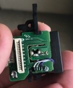
OK. This is what I am looking at. I'll take it off anyway.
Thanks
Attachments
- Home
- Source & Line
- Digital Source
- Shigaclone MKII Black - The builders Thread