If you can hear that you’re lucky/special(or your port is really small for what you intended ‘output’ to be? Or need to corner load/down fire /(???) the port and mask noises/help the whole thing work ‘best‘(build ‘TL’ version basically)Also varying tuning frequency with output level and temperature...
You're welcome!Thanks GM for the attachment.
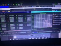
You have opened Netflix to watch movies, I imagine.
" But real speakers don't add seconds of delay. They only add milliseconds or tens of milliseconds of delay. So the real question comes down to "how much delay is just audible". If we were to gradually reduce the delay in the above experiment to zero there would come a point where the delay was no longer audible as a separate distinct sound. This would probably happen above the Hass limit of 30ms or so. As the delay is reduced further there would come a point where the "delay distorted" or "time smeared" version was indistinguishable from the original recording. This delay would represent the threshold of audibility for this delay curve and source material." 🙂
Actually, I haven't, only have OTA (antenna) TV, so no premium/streaming channels. Regardless, I understand and always a prime goal in my systems and any others that have the space/$$ to do it and why I use/recommend large ports (Av = Sd and sometimes even bigger) for a powerful vent BW, critically damped, so a moot point; or as one DIYer I did an Altec MLTL design for replicating live recordings of symphony's at one of Rome's premier venues he frequented put it; "bass harmonics on steroids" compared to any high end/mega buck speakers he'd tried/owned.
For driver specs that dictate an excessively long vent I use/recommend an inverse tapered (ML) TQWT.
Re delay, even with critical damping, the low tunings required to meet my goals make for high GD around/at/below tuning, but the lower the tuning the faster the decay, so by the time it gets up to these various frequency 'limits' its decayed to well below our hearing acuity and if sims are to be believed, right down there with sealed, so in the scheme of things, 'much ado about nothing'.
Time to move on.


Notice the 300cm :100cm ratio (odd harmonic?) 28.8/86.4hz…. Fix. Then it sh!ts the bed at 5/4(144hz (60cm?))Im so confused…. Some of the ‘worst’ designs have no group delay
https://www.parts-express.com/LaVoc...onal-Neodymium-Subwoofer-Driver-8-Ohm-293-756
Attachments

I very much doubt I could hear the level-induced shift but the temperature effects are very obvious on my workshop speakers which have seen a 30 Centigrade temperature range.If you can hear that you’re lucky/special(or your port is really small for what you intended ‘output’ to be? Or need to corner load/down fire /(???) the port and mask noises/help the whole thing work ‘best‘(build ‘TL’ version basically)
In a normal listening room the tuning frequency is stable - but the speaker changes over temperature of the voice coil and of course excursion. With WinISD you can quickly check what's happening at higher voice coil temps and that's A LOT difference. Not so important for gentle HiFi but for home cinema and PA that's something to have an eye on.Also varying tuning frequency with output level and temperature...
(I made tweeter voice coil measurements and calculations cause I need High SPL on one of my projects - measurement speaker. At about 10W voice coil temp of an T25A is calculated to 180°C. At 15W and about 280°C it got damaged. ScanSpeak SS 664000 can take more (but is less efficient) - at 15W I calculated 160°C of the voice coil - the membrane was 80°C at this point!
Calculation with measureing voltage and current and temp coef of copper. A 2dB power compression from heating the voice coil means about 150°C at the voice coil - somthing the glue and built of a good speaker can take without problems)
Back here, I wonder:
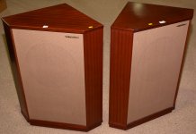
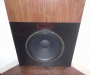
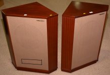
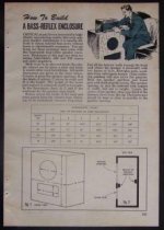
Regarding / the tuning tubes, I have found that the "vintage" option of "groove" (similar to the one attached) would be the easiest option to locate, (but not to build, the tubes are bought ready-made, here you have to work , but it won't be a problem for me )
one slot above and one below the speaker, 2 x 8 x 6.73 cm deep.
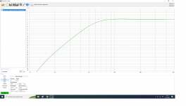
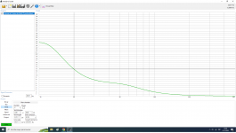
It would be the best practical and aesthetic option, I have played with the dimensions and Win ISD shows these results as the most convenient for this prism.
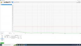
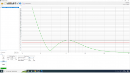
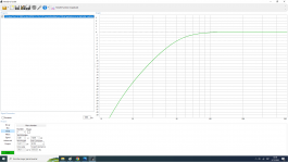
Tuned to FS of the speaker (28 Hz), 122 liters shows an F3 of 53, 44 Hz (better than sealed), the group delay playing 20 Hertz is 12.8 ms.
That can't be changed with DSP or EQ, but who cares if it's not audible? On the other hand, the 6.7 mm Xmax is only exceeded by applying 400 watts, being 8 mm and still does not exceed the 15 mm of XLim.
Thoughts ?
Regarding / the tuning tubes, I have found that the "vintage" option of "groove" (similar to the one attached) would be the easiest option to locate, (but not to build, the tubes are bought ready-made, here you have to work , but it won't be a problem for me )
one slot above and one below the speaker, 2 x 8 x 6.73 cm deep.
It would be the best practical and aesthetic option, I have played with the dimensions and Win ISD shows these results as the most convenient for this prism.
Tuned to FS of the speaker (28 Hz), 122 liters shows an F3 of 53, 44 Hz (better than sealed), the group delay playing 20 Hertz is 12.8 ms.
That can't be changed with DSP or EQ, but who cares if it's not audible? On the other hand, the 6.7 mm Xmax is only exceeded by applying 400 watts, being 8 mm and still does not exceed the 15 mm of XLim.
Thoughts ?
Attachments
Indeed, thermal power compression/distortion can be downright obnoxious, especially when wide range.I very much doubt I could hear the level-induced shift but the temperature effects are very obvious on my workshop speakers which have seen a 30 Centigrade temperature range.
'Groove'? Are the vertical slats box vents?Regarding / the tuning tubes, I have found that the "vintage" option of "groove" (similar to the one attached)
'Groove'? Are the vertical slats box vents?
Here is the answer, I think it will be even better, a single box tube above the speaker does not interfere with the bracing and has excellent air coupling between the inside and the outside. I have a question here, if I build it with wooden plates I should discount the thickness of the same to the total volume, correct? If so, it will be better to build it in brass or PVC of minimum thickness...... 🤔
Attachments
If I'm following, you subtract all the volume of the vent inside the box as if it was solid. Any particular reason you don't want any vent/floor loading to shorten the vent for a given tuning?Here is the answer, I think it will be even better, a single box tube above the speaker does not interfere with the bracing and has excellent air coupling between the inside and the outside. I have a question here, if I build it with wooden plates I should discount the thickness of the same to the total volume, correct? If so, it will be better to build it in brass or PVC of minimum thickness...... 🤔
1) I am not subtracting the volume of the vent, I am only introducing the net liters, discounting the volumes of the prehistoric stone - which I will remove -, the speaker and the bracing (the latter is not too precise because they are quite irregular shapes (ha, exotic? ) and I assume that WinIsd calculates the final dimensions of the vent taking into account that the cubic volume of the vent tube should be calculated in such a way that it gives a result corresponding to the litrage entered previously, but maybe I'm wrong...... 🤔
https://www.avsforum.com/threads/ca...ylindrical port having cross-sectional area A
2) There is no particular reason, only that in the bibliography that I have read they recommend that the space between the tube outlet (it does not matter what section it is, round, square or whatever) and the adjacent walls and/or floor it must be generous and in my case it is barely an inch.
It is for the same reason that moving a back-vented cabinet too close to the wall is not recommended.
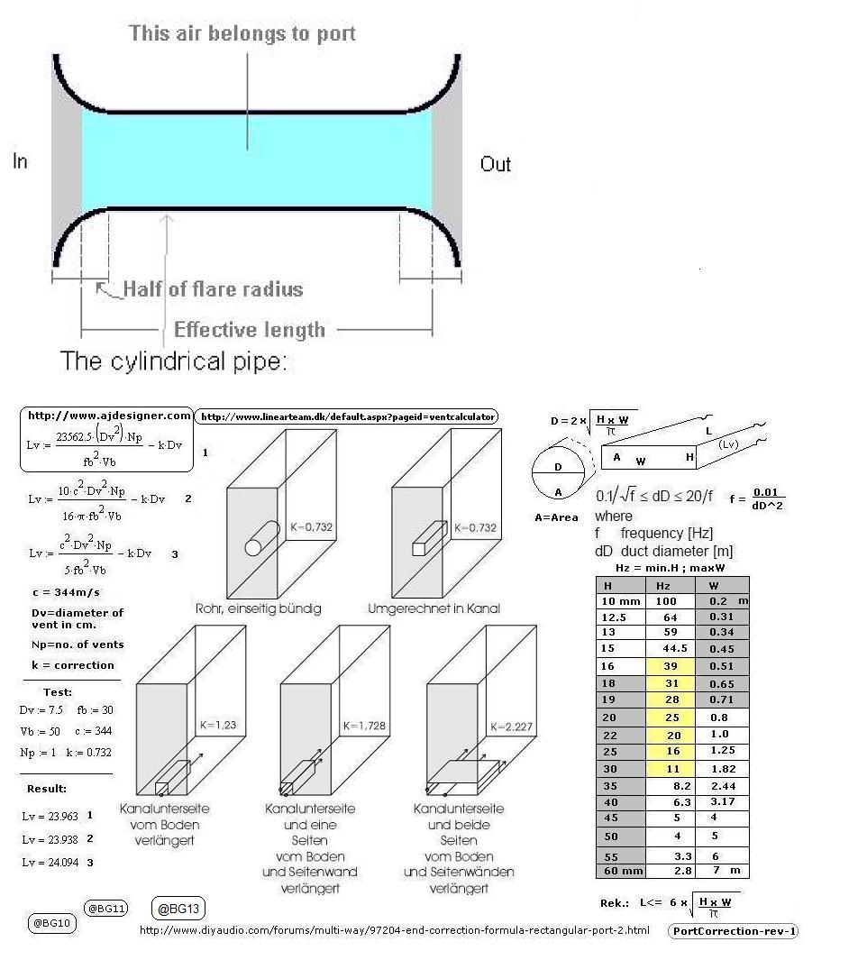
Well, it must be 'generous' if the program doesn't calculate a near/at floor, wall end correction that shortens it. 😉
Humm, I guess I won't go further than the results that Win Isd shows for my project. Your attachment clearly shows that the duct located in the position I chose has the same Q whether it is circular or square in section, this is 0.732. But if you have a definitive and superior result to help me, since you are so good with math formulas and I am not, could you calculate exactly the duct for me? Think of it as your own project. You have all the data you need, if it is not clear, just ask me ! 🙂
Yes, you're fine if WinISD is accurate enough, I was referring to when near a solid boundary where depending on its size/shape can significantly shorten it.
- Home
- Loudspeakers
- Subwoofers
- Sealed subwoofer to bass reflex, what do I gain and what do I lose ?